MOTOR VEHICLES. The term “motor-car” is one which was primarily employed in America to denote the car or carriage containing the electro-motor used for propelling an electric tramcar or train of carriages on rails, but of late years it has been more usually applied in Great Britain to light automobile or mechanically-propelled carriages running on common roads. On the continent of Europe and in the United States the usual expression for these vehicles is “automobile”; the term “autocar” has also been employed. We shall deal here first with the history of mechanically propelled carriages, and with the evolution of the lighter type used for conveying people for pleasure and sport; and secondly with the heavier type used for the carriage of goods.
Light Vehicles.—The first practical steam carriage was made by Richard Trevithick in 1802 (fig. 1), though Cugnot had produced a rudimentary one in France in 1769; but very little was done in this direction until 1824, from which date a number of these vehicles were constructed and used with considerable success, taking the form of stage coaches propelled by steam, and weighing some 3 or 4 tons unloaded. Some of these ran regular passenger services, notably between Cheltenham and Gloucester, attaining average speeds of 10 to 14 m. per hour; but great opposition was met with owing to the narrow prejudice of those whose interests related to horse-haulage, and every obstruction was offered in the shape of prohibitive tolls and legislative enactments. The result was that steam carriages were driven off the roads in favour of railways, although the select committee of the House of Commons appointed in 1831 to inquire into the subject reported completely in favour of their adoption (as did also that of 1873). In 1861 the first Locomotives on Highways Act was passed, but the crushing blow came in 1865, when the legislature prescribed (1) that the number of persons required to drive the locomotive should be increased to three; (2) that a man should precede with a red flag; (3) that the maximum limit of speed should be reduced to 4 m. per hour; and (4) that they should be forbidden ever to blow off steam, &c. These restrictions were confirmed rather than relieved by the 1878 act. Although these acts were created to deal with heavy traction, the famous 1881 appeal in the court of queen’s bench placed every type of self-propelled vehicle, from a traction engine down to Bateman’s steam tricycle, under their narrow limitations. This resulted in the development of the heavy traction engine, and light motor vehicles were little more heard of in Great Britain. There were a few exceptions, however, notably the steam vehicles of Rickett (1860), Carrett (1861), Tangye (1862), Yarrow (1862), Holt (1866), Todd (1870), Perkins (1870), Mackenzie (1875) and Blackburn (1878), and some electrical carriages made by Elwell (1884), Ward (1886) and Volk (1888). An important departure was that of Butler, who constructed in 1885 what is believed to be the first vehicle (a tricycle) propelled by an internal combustion engine in England (fig. 2); he used the vapour of benzoline exploded electrically. Later, Roots successfully employed heavy oil, as did Knight. The chief prohibitory clauses of the acts were repealed in 1896, when the development of the internal-combustion engine had opened up entirely new prospects and suggested new possibilities.

Fig. 1.—Trevithick’s Steam Carriage of 1802: side view and plan.
Gottlieb Daimler’s invention in 1885 of the internal-combustion motor using petroleum spirit was the first step towards the production of the modern self-propelled road vehicle, the next step being the recognition in 1887 of the advantages of Daimler’s system by M. Levassor and his application of that system to the propulsion of a carriage. In the nine years that immediately followed French manufacturers spent large sums of money in experimenting with and developing the motor-car, and by 1896, when the Enabling Act was passed, there were a few practical vehicles in England but, perhaps, fewer probable buyers. British makers, starting as they did in the wake of the French manufacturers, were able to profit by the experience gained by the latter, and thus to avoid many otherwise inevitable mistakes; they may not be able to claim to have originated many of the fundamental details of the modern motor-car, but their experience was gained at a comparatively small cost.

Fig. 2.—Butler’s Motor Tricycle of 1885.
Gottlieb Daimler’s engine marked a great advance in the production of a source of motive power, for its efficiency was large as compared with its total weight, whilst the simplicity of its fuel system brought it within the scope of the person of average mechanical instincts and intelligence, for, even in its early days, the internal-combustion motor did not demand that its user should possess an intimate knowledge of engineering. Daimler fitted one of his motors to a bicycle in 1885, and afterwards applied the system to the propulsion of boats, one or more of which were running on the river Seine in connexion with the Paris Exhibition of 1887. It was this fact that brought the invention to the notice of M. Levassor, of the firm of Panhard & Levassor, makers of wood-working machinery, who saw the possibilities of its application to the propulsion of a road carriage. MM. Panhard & Levassor secured the French patents from Daimler, and M. Levassor devised the transmission system which, as far as its general scheme is concerned, is unaltered to-day, despite many efforts on the part of skilful inventors and designers to secure something better. M. Levassor placed the engine in front, the axis of the crank-shaft being parallel with the side members of the frame of the vehicle. The drive was taken through a clutch to a set of reduction gears and thence to a differential gear on a countershaft from which the road wheels were driven by chains. With all the modifications of details, the combination of clutch, gear-box and transmission remains unaltered, so that to France, in the person of M. Levassor, must be given the honour of having led in the development of the motor-car.
Progress in the improvement of design was slow until the year 1894, when a great impetus was given to the French industry by the organization, by the Petit Journal, of a trial run of motor vehicles from Paris to Rouen. The measure of success attained. by the cars caused considerable surprise, and in the year 1895 a race was organized from Paris to Bordeaux and back, a distance of 744 m., when the winning vehicle covered the journey at a mean speed of 15 m. per hour. From that date onward, until 1908, racing played an important part in the development of the motor-car; in fact, it is not going too far to say that, up to 1904, it played a vitally important part therein. The effect was a rapid development in speed, efficiency and reliability, and others besides the sportsman and the individual seeking for new sensations were attracted towards the new vehicle. Racing was not indulged in in England or Scotland, the authorities having no power to close the roads for the purpose.

Fig. 3.—The 40–50 h.p. Six-cylinder Rolls-Royce Pullman-Limousine.
In July 1902, Mr S. F. Edge, driving a 50 h.p. Napier car, won the Gordon-Bennett Cup in the course of the open race from Paris to Vienna. This trophy has played an important part in the history of the motor-car. It was offered for competition among cars, entered by recognized National Automobile Clubs, no more than three cars being permitted to represent a country, and every car had to be built entirely in the country of its origin. The length of the race had to be not less than 500 kilometres (31012 m.). The first two races in 1900 and 1901 had been won by French cars and, as these contests had been run concurrently with the big city-to-city races, the importance of the Gordon-Bennett race was overshadowed. But it stood out in bold relief when an English car wrested the international trophy from its French rivals in 1902. The Automobile Club of Great Britain and Ireland (now the Royal Automobile Club) at once secured parliamentary sanction for the use of certain roads in Ireland for a limited period, and proceeded to organize a race worthy of the issue at stake. The race was won by the Mercédès car, the latest production of the famous house of Daimler.
The Mercédès car set quite a new fashion, for it showed advancement in a large number of its mechanical details, and many of these details were either copied or used as the basis for radical changes in previously-existing designs. So far as British makers were concerned, the Mercédès fashion was allowed to predominate, but some of the older French makers were less willing to follow the lead of the great German house. This fact assisted the British makers to forge ahead in their competition with the French. But the great factor in the triumph of British motor engineering arose from the fact that, in England, there was a great wealth of knowledge concerning the properties of steels and steel alloys, and that knowledge, which was advancing all the time, was turned to such good use that it is safe to say that, in only the very best of French cars is the same strength and efficiency obtained from the same weight of metal as would be used in the construction of quite a number of British cars. Lightness of moving parts has led to increased engine efficiency and to economy of fuel, whilst the inert parts of the mechanism—the frame and other fixed details—by being lighter, call for a smaller expenditure of power to overcome their inertia. Apart from the employment of special steels for motor-car construction, in which England took a leading part, many improvements in design and method have originated in Great Britain. For instance, the multiple-disk clutch, which permits a car to be started without shock, is an English invention, as are the detachable wheel, the spare wheel and the six-cylindered engine. The latter, introduced by the Napier Company and employed extensively by them, by Rolls-Royce and others, has exerted a great influence upon British tastes, because it created a growing dislike to noise, one of the consequences being the rapid development of the silent car.
The representatives of Great Britain in the Gordon-Bennett race of 1903 were selected by means of a series of eliminating trials, and in 1904 and 1905 races were held annually in the Isle of Man for the same purpose. In the years 1906, 1907 and 1908 races were held in that island with such limitations on fuel or on the diameter of the cylinders as were calculated to encourage the development of small but efficient transmissions, and it has been conceded generally that these races served an extremely useful purpose.
Concurrently with its development into a reliable, silent, odourless and smokeless power-propelled vehicle, the motor-car gradually came into more general use. It no longer appealed only to a few but gained converts daily, and its final triumph came when it began seriously to displace the horsed vehicle. becoming the private carriage of the wealthier classes to be used on all occasions.
If the motor-car in the guise of a private carriage has developed at an astonishing rate, its adaptation to the needs of the community, as a public service vehicle, has been even more rapid. The first cabs placed on the streets of London in 1903 were by no means a success, but the cabs constructed by the French house of Renault and first introduced in London in 1906 rapidly effected a revolutionary change in the means of individual transport. Apart from the improved speed of the motor-cabs, they gained popularity because of the use, on each one of them, of the taximeter, showing at a glance the amount of the fare, thus preventing overcharge on the part of the driver. One effect of the employment of motor-cabs and motor-omnibuses has been to reduce slightly the total number of vehicles, and to quicken a large volume of the traffic; it is now being recognized that to increase the speed of the whole of the traffic of London by about 5 m. an hour is practically equivalent to doubling the width of the whole of the main streets.
The new British act of 1903, which was enacted for three years only, was, during the parliamentary session of 1906 and subsequent sessions, continued from year to year because of the difficulty that was experienced in reconciling conflicting views about the control of motor-cars. The 1903 act raised the speed limit to 20 m. per hour and gave the local government board power to close to motor traffic such roads as, on inquiry, might be deemed unsuited therefor, and to impose a speed limit of 10 m. an hour or less in dangerous places, such as narrow streets in a town or through a village. A few serious accidents in England, and many abroad, have kept alive the fear that the motor-car is a dangerous vehicle that should be restrained or held in check by stringent legislation. Thus from 1904 onwards, the motorist was under continuous police supervision. Police traps, or measured distances, over which the motor-car is timed by the police, were established in most of the counties of England, and, whilst, without a doubt, many real offenders were caught, it is equally true that many an innocent driver was unfairly accused, whilst motorists guilty merely of technical infringements of the law were summoned.
The attitude of the police in showing little or no leniency in the application of the law probably, however, did good in other directions, although these were not contemplated either by the law-givers or the police themselves. It considerably limited the use of excessively powerful cars (for example, a 60 or 90 h.p. car that could easily attain 60 m. an hour), and experience has demonstrated the fact that, intersected as England is with a network of narrow roads carrying considerable traffic, there is little opportunity for the full power of such a car to be used. The result has been that the comparatively low-powered vehicle has been developed in efficiency, bringing with it the advantages of economy in running, simplicity of mechanical details, cheapness of maintenance and ease of control and management.
The principle of the internal-combustion engine has not been altered since Daimler’s day, but the mechanical details of the engine have undergone constant revision and improvement, until in 1910 it was safe to say that a four-cylindered engine, with a cylinder bore of 4 in., constructed, we will presume, in 1899, might have developed 20 h.p. or less, Whereas engines of the same cylinder bore made in 1908 and 1909 actually developed 60 h.p. and more, and the attainment of even greater efficiency was in sight in 1910. Experience showed that the saving of weight meant greater economy in fuel and also in tires, the two principal items in the upkeep of the motor-car. Engine design has undergone unceasing improvement, and constructional methods have been continuously advanced, with the end in view of attaining lightness, not only in the moving parts, but in the inert parts. Lightness in reciprocating parts, such as the pistons, connecting rods and valves, has enormously improved crank-shaft speed. Cylinder castings are now made far lighter, whilst the water jacketing, for dissipating the excess of heat from the cylinder walls, is now of sufficiently ample proportions and, in consequence, better lubrication of the cylinder walls can be maintained. This again conduced to piston speed. The induction valves of engines of the earlier types were opened under atmospheric pressure, the reduced pressure in the cylinder, caused by the downward movement of the piston, enabling the pressure of the outer atmosphere to open the valve against its light spring, and to carry in a charge of the carburetted air that constituted the explosive mixture. But it was found that the automatic or atmospheric inlet valve opened late on the induction stroke and closed early, so that the engine only received an attenuated charge. One of the earliest improvements in engine design, therefore, was the employment of the mechanically-operated inlet valve operated by a cam exactly as the exhaust valve is operated. This valve could be fully opened as soon as the piston had begun its downward or induction stroke, and could be held open during the momentary period when the piston was at rest at the bottom of the stroke, thus ensuring a full charge of explosive mixture. The method of exploding the charge in the cylinder has undergone revolutionary changes. The first method, that of heating the exterior of a closed tube connected with the cylinder, quickly gave way. to electric ignition because it was found that the charges could not be exploded by the hot tube until the piston had reached the top of its stroke, and, at the comparatively high piston speed of these engines, the piston had moved some distance on its downward stroke before the exploded gas had begun to expand. Electric ignition was an improvement because it enabled a “lead” to be given to the explosion, a low voltage current (from four to six volts of about one ampere being sufficient for the purpose) being automatically switched on to the primary circuit of a coil, the induced current in the secondary circuit being of a voltage sufficiently high (calculated at from 5000 to 10,000 volts of a very small amperage) to jump across a, gap left in a sparking plug inserted in the cylinder. By rotating the body of the switch (called the contact breaker) the ignition could be timed to suit exactly the speed of the pistons and, in this way, greater piston speed was obtainable. The great development of this system was the introduction by Mr F. R. Simms, in conjunction with Herr Bosch, of the magneto machine, known as the Simms-Bosch magneto, the prototype for many such appliances. This machine, in its simplest elements, produces a low voltage current (assumed to be of about eight or ten volts) by the rotation of an armature in the magnetic field of a set of magnets, the rotation being effected through the timing-gear wheels of the engine. The low tension current is conveyed through a primary circuit inducing the secondary current which is employed for igniting the charges. The advantages of the magneto are, firstly, that the primary current is created by the engine, and that the need for an accumulator as a source of that current is avoided and, secondly, that the spark is more efficient because the faster the armature is revolved the more intense is the primary current and the induced current, consequently, the charge is ignited more rapidly. The magneto machine has almost entirely displaced the accumulator system for ordinary running, although, as the latter makes for easier starting, it is often fitted as an addition.
Great gain in power has been secured from improvements in the lubrication of the internal-combustion engine. It is now recognized that a small supply of oil to the journals and bearings of such an engine is insufficient, but in the early days it was found difficult to give the journals and bearings more oil without too much getting on to the cylinder walls, because the latter were lubricated by the oil that was thrown on to them by the spinning action of the webs of the crank-shaft and by the connecting-rod ends, these latter dipping into a well of oil in the lower part of the crank-case. The modern method has overcome this difficulty. The cranks and connecting-rod ends no longer dip into the oil, for the latter drains away into a sump or reservoir below the base of the crank chamber. Thence it is passed through a filter and pumped to ducts which convey the oil under pressure to the crank-shaft journals. Sometimes it is conducted thence along ducts bored in the crank-shaft and through the webs and crank-pins, whence it feeds the connecting-rod bearings, enough squirting out to splash on to the cylinder walls. Sometimes, a shallow trough is placed under each connecting-rod end, to hold oil to a certain depth and no more, and a scoop on the big end collects enough oil to effect the lubrication of the connecting-rod bearings and cylinder walls. The aim has been to secure definite lubrication of all moving parts, and, at the same time, to prevent oil being present on the cylinder walls in such quantities as will permit the piston to carry it up into the combustion chamber. Any oil present in the combustion chamber is burnt during the explosion, but, its combustion being imperfect, smokiness of the exhaust is the result. By reducing the oil on the cylinder walls to the minimum necessary for lubrication, smoking has been abolished, whilst clogging, or carbonizing, of the valves has been materially reduced.

|
| The 40–50 h.p. Six-cylinder Rolls-Royce Engine (valve side, showing also position of magneto). |

|
| Fig. 4.—The 40–50 h.p. Six-cylinder Rolls-Royce Engine (carburettor side, showing also high-tension distributor, and position of centrifugal water pump). |
Methods of carburation have also undergone improvement, so that the carburation shall not materially vary with varying engine speed. The only other feature in the engine that calls for mention is the method of cooling. With the introduction of the honeycomb type of radiator, by which the water is made to flow through canals an eighth or a sixteenth of an inch wide, the efficiency of the cooling system has been doubled because of the large amount of surface, in a given size of radiator, for dissipating the heat. A fan is generally employed, either situated behind the radiator and driven by the engine, or the flywheel is vaned so as to induce a current of air through the radiator. To deal now with the transmission mechanism, the drive is taken through a clutch and gear-box as in the earliest days, but, for the final drive, chain transmission to the road wheels running on a fixed axle has largely given place to propeller drive on to a live axle. The leather-faced conical clutch, although still employed, has in many cases given way to the multiple-disk clutch in which a number of disks bearing against each other, either flat in section, or (as in the Hele-Shaw clutch) having annular tapered grooves, are contained in an oil-tight box. These plates are capable of being separated laterally from each other when “out of gear,” or brought into frictional contact with each other when it is desired to start the car. Metal-to-metal cone clutches expanding metal shoe clutches, single metal plate clutches and coil spring clutches have all at some time found favour with designers wishing to avoid a leather clutch. Hydraulic and electro-magnetic clutches have also been tried, but these have not gained any vogue. In the matter of the gear-box, the sliding into mesh of the gear-wheels as employed by Levassor is still the standard practice although that pioneer himself regarded the method as barbarous, and looked upon it as a mere temporary expedient. But details of the gear-box have materially improved. A single lever is usually employed for engaging any of the forward gears or the reverse, so that the mistake of simultaneously engaging a reverse and a forward gear is not possible. The spur-wheels are generally mounted in pairs on two sleeves, so that, by means of a selector mechanism that compels one sleeve to be brought to the neutral position before the other can be moved, no two gears can ever be engaged together. By means of “dog clutches,” the clutch shaft can generally be coupled direct with the bevel-wheel driving the back axle the “drive” on the highest gear being thus transmitted without passing through any spur-wheels. This reduces noise and frictional losses. Except for cars of great weight, chain transmission is fast dying out, the power being generally transmitted through a propeller shaft (with universal joints at one or both ends) to a bevel-drive on the back axle; such axle being divided into two revolving or live axles carrying the differential gear between them. The bevel-wheels, differential gear and live axles are enclosed and run in a lubricant.
Wire suspension wheels are growing considerably in favour, a saving in weight being thus effected. The liability of the pneumatic tire to deflation, through a puncture or burst, has led to the introduction of detachable rims and detachable wheels. The detachable rim is borne on the periphery of the wheel (which is bonded) and secured in position by various methods. When the tire is punctured or damaged the rim and tire are removed bodily and replaced by a spare rim with its tire already in position and inflated, a change capable of being effected in five minutes or less. The detachable wheel is mounted upon a shell which fits over and is secured to a sleeve, which latter turns and is secured upon the fixed axle. In the case of tire trouble, the wheel intact is removed from the sleeve (which in the case of a driving-wheel carries the driving fittings, the brake-drums, &c.) and a duplicate wheel is substituted. The pneumatic tire has undergone continuous improvement, particularly in the matters of the selection of the material and the proportioning of the strength of the “body” to the work which the tire is to be called upon to perform. Various methods have been devised for the prevention of skidding or “side-slip” on greasy surfaces, and, whilst certain mouldings on the rubber treads have proved advantageous, the method most adopted is that in which a large number of steel studs stand about a quarter of an inch above the surface of the tire.

Fig. 5.—Plan View of the 40–50 h.p. Six-Cylinder Rolls-Royce Chassis (1910 type).
It will be seen that the general lines of the car of 1889 have not required to be radically altered. Every detail has been improved so that the cars are more efficient, easier to control and manage, and infinitely more comfortable, but, in essence, Levassor’s scheme is as good to-day as it was when planned by him.
The steam car is made by five or six British manufacturers at the most, whereas the actual manufacturers of petrol cars in Great Britain numbered at the end of the year 1909 about seventy, whilst some four hundred other firms were actively engaged in the construction of cars and their parts, accessories and sundries. But the steam car appeals to those men who are or have been steam engineers, and to them the management of the steam generator and the burners constitutes no difficulty. The limitations under which the early steam car laboured have, in the main, disappeared, for the modern steamer can travel nearly as far without requiring to refill the boiler as a petrol car can travel without replenishment of the fuel tank. The electric car is still the luxury to be employed in towns and in covering short distances, for the weight of the accumulators has not been greatly reduced, despite sensational announcements made from time to time.
An interesting feature of the motor movement has been the steady growth in popularity of the motor cycle. The motor tricycle was developed up to the year 1903, and then gradually became displaced by the motor bicycle, which had been introduced in 1901. Motor bicycles gradually increased in popularity, until in numbers they were in excess of cars. The standard machines of 1909 had an air-cooled motor of one, two or even four cylinders (according to the choice of the riders) developing some 3 to 8 h.p. with magneto ignition and belt drive. The engine was usually started by the rider running alongside the machine, and causing the machine to rotate the crank-shaft through the belt and pulley until the initial explosion was obtained, when he would jump into the seat. Trailers were employed at first for carrying passengers, but, the length of the combined vehicle being between nine and ten feet, a side-car, placed at the side of the cycle and secured thereto by detachable fittings, largely displaced the trailer and also the “fore-car,” in which the passenger was carried in a body placed in front of three- and four-wheeled cycles.
The rapid growth of the motor movement in Great Britain may be judged from the fact that by the 30th of September 1905 the number of motor vehicles of all kinds registered had totalled to 74,038, and by the 30th of September 1908, three years afterwards, to no less than 154,415. Of these, 137,323 were registered in England and Wales, 10,907 in Scotland, and 6185 in Ireland. 71,405 were private motor-cars; 12,104 were trade motor-cars; 5880 were public service vehicles and 65,026 were motor cycles.
A year later (Sept. 30, 1909) the figures showed a further remarkable increase, the total number of vehicles registered in the United Kingdom being 183,773, giving an increase of 29,358 in the year. Of these, private motor-cars numbered 84,840; trade motor-cars 15,181; public service vehicles 8752; and motor cycles 75,000. The numbers registered in England and Wales Were: 74,748 private motor-cars; 13,961 trade motor-cars; 8131 public service vehicles and 66,341 motor cycles, or 163,181 in all. The figures for Scotland were: 6157 private motor-cars; 1056 trade motor-cars; 584 public service vehicles and 5296 motor cycles or 13,093 in all. The figures for Ireland were: 3935 private motor-cars; 164 trade motor-cars; 37 public service vehicles and 3363 motor cycles, or 7499 in all. In the year private motor-cars in the United Kingdom increased by 18·8%; trade motor-cars by 25·4%; public service vehicles by 48·8%, and motor-cycles by 15·3%.
It is possible to obtain a better idea of the number of motor vehicles in use from the returns of the commissioners of inland revenue. The total number of privately-owned cars for which licences were issued in 1908 was 48,019, of motor cycles 35,784, and of motor-driven hackney carriages 17,300. These figures may be compared with the registration figures already given for the year ending the 30th of September 1908. As accounting partly for the difference, a certain proportion of the registered vehicles (seeing that the figures include all vehicles in use on and after the 1st of January 1904, less those in respect of which the registrations have been cancelled) must have fallen into disuse and some vehicles will have been sold out of the country, whilst others will have been sold and re-registered with different authorities. But the life of the mechanism of a car, in one form or another, is of considerable length (there were, for instance, in use in 1910, as commercial vehicles, motor chassis that were put on the road in 1896), and it is considered that many registered but unlicensed cars remain for years capable of rendering useful service in emergencies or on special occasions, such as at election periods.
In 1906 an act of parliament authorized a census of production, which was taken in 1908, the statistics relating to 1907. These figures show that the output of complete motor vehicles in the United Kingdom in that year was 11,700 completed cars and chassis, and 3600 motor cycles, the total value of the productive work done in the motor trade being £6,327,000 inclusive of repair work and the production of parts and accessories.
The number of cars and chassis imported into and retained in the country (those imported and afterwards re-exported being excluded from the statistics) in 1909 was 7747 as compared with 6530 in 1908. The absence of a classification, in 1907 and previous years, for chassis prevents further comparison in the matter of numbers, but taking the value of the motor-cars, parts and accessories imported into and retained in the United Kingdom, there is a total of £4,170,121 in 1907, £3,753,140 in 1908, and £3,922,781 in 1909; the average value per car falling from £432 in 1907 to £333 in 1909. The value of the motor cycles and their parts imported into and retained in the country was £71,101 in 1907, £52,206 in 1908, and £48,327 in 1909.
The number of British made cars and chassis exported in 1909 was 2802 as compared with 2441 in 1908, and of British made motor cycles 1893 in 1909 as compared with 1048 in 1908 and 800 in 1907; the total value of the exports of cars, parts, chassis and motor cycles in 1909 being £1,669,361 as compared with £1,315,913 in 1908 and £1,378,180 in 1907.
With the growth of the motor-car movement there have, naturally, been great developments in the outside industries catering for the motorist. Most affected by that movement has been the oil trade, considerable changes having taken place. In the distillation of crude petroleum for the production of lamp oils, &c., quantities of volatile spirit were obtained, the outlet for which, formerly, was small, as the spirit was mainly used for cleaning purposes. With the introduction of the petrol motor this spirit came into demand, and, as the demand increased, the situation changed and the crude petroleum had to be distilled mainly for spirit, thus leaving a surplus of the heavier oils. The situation was largely met by a gradual conversion of the petrol-consumers from spirit of ·680 specific gravity to a spirit of ·715 specific gravity, whilst for commercial motors even heavier grades were employed. The quantity of ·715 spirit obtainable from a given quantity of crude oil is considerably greater than the quantity of ·680 that could be produced, so that a better balance between the demand for motor spirit and that for lamp oil has been effected. The total quantity of motor spirit used in the United Kingdom in 1909 was 60,000,000 gallons, of which about one-half came from the Dutch East Indies, whilst a third came from America. Rumania supplied about 6,000,000 gallons and Russia about 3,000,000 gallons. Large quantities of lubricating oil were obtained from America, whilst the remainder (about one-tenth of the total) came from Russia.
France is the centre of the motor-car industry in Europe, and up to the year 1906 it undoubtedly led in the production of motor vehicles, but in that year the United States of America, as we shall have occasion to note, took the lead. The number of private cars in use in France had risen from 1438 in 1899 to about 23,000 in the year 1909, whilst industrial vehicles have increased even more rapidly in number. The following figures are obtained from the taxation schedules:—
| Year. | Number of Vehicles in use. | Total. | |
| Pleasure Cars. | Industrial Cars. | ||
| 1899 | 1,438 | 234 | 1,672 |
| 1900 | 2,354 | 543 | 2,897 |
| 1901 | 4,427 | 959 | 5,386 |
| 1902 | 7,353 | 1,849 | 9,207 |
| 1903 | 9,922 | 3,062 | 12,984 |
| 1904 | 12,519 | 4,588 | 17,107 |
| 1905 | 15,011 | 6,532 | 21,543 |
| 1906 | 17,358 | 8,904 | 26,262 |
| 1907 | 19,601 | 11,685 | 31,286 |
| 1908 | 22,252 | 15,334 | 37,585 |
| 1909 | 26,000 | 20,000 | 46,000 |
The figures for the year, in the absence of the official return, are estimated.
The average h.p. per car (pleasure vehicles) has steadily risen from 5·06 in 1901 to 13·28 in 1908, the number of cars seating more than two persons having increased in greater proportion than those seating one or two persons.
The export of French motor vehicles had risen in value from 4,259,000 francs in 1899 to 144,352,000 francs in 1907. In 1908 the exports fell to 127,300,000 francs, and in 1909 an improvement to about 145,594,000 francs had taken place. The imports of foreign motor vehicles to France rose from 473,000 francs in 1899 to 8,676,000 francs in 1907, and since that period there has been an annual decrease.
In Germany the number of motor vehicles of all kinds in use on the first of January in each year is shown in the following table:—
| Year. | Number of motor vehicles. |
| 1907 | 27,026 |
| 1908 | 36,022 |
| 1909 | 41,729 |
| 1910 | 41,941 |
In 1910 45% of the total consisted of motor cycles, 49·3% consisted of pleasure vehicles and 5·7% consisted of commercial vehicles, the proportion of pleasure Vehicles having consistently risen in the four years.
The development of motoring and of the motor industry in the United States has been exceedingly rapid. As good roads multiply and extend the use of cars must be still further developed. The American farmer has discovered that he can make considerable use of the motor-car in connexion with his industry, and this fact largely accounts for the demand for high-wheeled buggies, and for vehicles having ample clearance between the machinery and the road level.
In the early days of the movement the American taste inclined towards steam cars, and the mistaken view that the vehicle driven by an internal-combustion engine could never be made to run as silently as a steam car was generally held. But in Europe the petrol engine became refined so rapidly that its equality with the steam engine in the matter of silence, together with its superiority in the matter of simplicity and suitability for the man who is not an engineer, soon created for it a popularity that prevented any material expansion of the business in steam cars. The makers of steam cars in America are able to cope with the major portion of the world’s demand for this particular type of vehicle.
The introduction of the Dingley tariff, assessing an import duty of 45% ad valorem on motor-cars (in the classification of “manufactured metal”), added to a further charge of about 5% for freight, encouraged American capitalists to embark upon the manufacture of motor-cars, and in 1899 thirty manufacturers produced 600 cars. In 1909 the number produced by 200 concerns was 114,891. Set out in tabular form such figures as are obtainable are very striking:—
| Cars Produced. | ||
| Year. | Number. | Value. |
| $ | ||
| 1899 | 600 | 1,290,000 |
| 1903 | 10,576 | 16,000,000 |
| 1904 | 13,766 | 24,500,000 |
| 1905 | 20,787 | 42,000,000 |
| 1906 | 23,000 | 50,000,000 |
| 1907 | 42,694 | 105,000,000 |
| 1908 | 49,952 | 83,000,000 |
| 1909 | 114,891 | 135,000,000 |
| 1910 | 200,000 | 225,000,000 |
The number of cars for 1906 is approximated and the number of cars and their value for the year 1910 are based upon the estimated output of the various manufacturers. In 1908, whilst the number of cars constructed showed an increase over the number for 1907, the total value had decreased owing to the commercial crisis of that year. In 1909 those manufacturers who had formed the Association of Licensed Automobile Manufacturers, and who agreed to recognize the validity of the Selden patents, paid licence fees upon 94,891 cars, the remaining 20,000 cars being estimated as the output of the concerns that did not belong to the association.
Of the 200,000 motor vehicles estimated to be constructed in 1910, 165,000 were to be petrol-driven pleasure cars, 30,000 were to be petrol-driven high-wheeled buggies, and 5000 steam and electric carriages and commercial vehicles.
The history of the Selden patent may be given briefly A patent was applied for on the 8th of May 1879 by George B. Selden, of Rochester, New York, for a gas compression engine for propelling road vehicles. A patent was granted to him on the 5th of November 1895 for an improvement in road engines, and he claimed that any vehicle propelled by an internal-combustion engine, manufactured since that time, was an infringement of his rights under the patent. At the commencement of the year 1910, 71 manufacturers admitted this claim and paid to the Association of Licensed Automobile Manufacturers 112% of the catalogue price of their products as licence fees.
The imports of motor vehicles into the United States of America are not numerous, as will be seen from the following figures:—
| 1902 . . | 265 cars imported | 1906 . . | 1433 cars imported |
| 1903 . . | 267 ,,,, | 1907 . . | 1017 ,,,, |
| 1904 . . | 605 ,,,, | 1908 . . | 1387 ,,,, |
| 1905 . . | 1054 ,,,, |
The exports rose from $599,927 in value in the year 1902 to $5,502,241 in 1907 with a falling off to $5,277,847 in 1908.
Authorities.—Baader, Die Unmöglichkeit Dampfwägen auf gewöhnlichen Strassen mit Vortheil einzuführen (Nuremberg, 1835); Badminton Library, Motors and Motor Driving (London, 1902); Beaumont, Motor Vehicles and Motors (London, 1900), and “Mechanical Road Carriages” (Cantor Lectures, London, 1895); Brander, L’automobile de 1822 à 1835 (Brussels, 1898); Farman, Les Automobiles (Paris, 1896), and Autocars, Cars, &c. (London, 1896); Fletcher, Steam Locomotion on Common Roads (London, 1891); Gordon, A Treatise on Elementary Locomotion by Means of Steam Carriages on Common Roads (London, 1832, 1834 and 1836; Gore, Propulsion of Carriages on Common Roads by Power other than Animal Power (London, 1893); Graffigny, Manuel pratique du constructeur et du conducteur de cycles et d’automobiles (Paris, 1900); Grand Cartaret, Le Voiture de demain (Paris, 1898); Gray and others, The Motor Year Book (London, 1905 and 1906); Guerdon, Manuel pratique du conducteur d’automobiles (Paris, 1897); Gurney, Steam Carriages on Turnpike Roads (London, 1832); Hancock, Steam Carriages on Common Roads (London, 1838); Jenkins, Power Locomotion on the Highway (a guide to the literature; London, 1896); E. H. Knight, American Mechanical Dictionary, “Road Locomotives,” vol. iii. (New York, 1876); J. H. Knight, Notes on Motor Carriages (London, 1896); Lardner, The Steam Engine (7th ed., pp. 419–440; London, 1840); Lavergne, Manuel théorique et pratique de l’automobile sur route (Paris, 1900); Lavergne and Hasluck, The Automobile (London, 1902); Lieckfeld, Die Petroleum- und Benzinmotoren (Munich and Leipzig, 1894); Little, Automotor and Horseless Vehicle Journal (London, 1898); Lockert, Traité des véhicules automobiles (4 vols., Paris, 1896–1897); Petroleum Motor Cars (London, 1898); Maceroni, Facts concerning Elementary Locomotion (2nd ed., London, 1834); Powers and Qualities of Maceroni’s Steam Carriage Demonstrated (London, 1835); Steam Power on Roads, &c. (London, 1835); Mann, New Method of Propelling Locomotive Machines (compressed air) (London, 1830); Medhurst, A New System of Inland Conveyance for Goods and Passengers (compressed air) (London, 1827); Milandre and Bouquet, Traité de la construction, de la conduite et de l’entretien de voitures automobiles (4 vols., Paris, 1898–1899); O’Gorman, Motor Pocket Book (London, 1904); Perissé and Godfernaux, Traction mécanique sur rails et sur routes (Paris, 1900); Rose, A Record of Motor Racing (London, 1909); Salomons, The Horseless Carriage (London, 1895); Saunier, L’Automobile théorique et pratique (2 vols., Paris, 1899–1900); Sennett, Horseless Road Locomotion (London, 1900); Smith, History of English carriages and Motor Cars Tunbridge Wells, 1876); S.P.T.A. (Self-Propelled Traffic Association), Trials of Motor Vehicles for Heavy Traffic (Liverpool, 1898, 1899, and 1901); Sir H. Thompson, The Motor Car: its Nature, Use, Management (London, 1902); Wallis-Taylor, Motor Cars or Power Carriages for Common Roads (London, 1897); R. B. Whitman, Motor-car Principles (New York, 1909); Witz, Moteurs à gaz et a pétrole, vol. iii. (Paris, 1899); Yarrow, “On Steam Carriages,” Proc. Soc. of Eng. (London, 1863); Young, The Economy of Steam Power (London, 1860); Filson Young, The Complete Motorist (London, 1904); vol. xxxvi. (Head) “Steam Locomotion on Common Roads,” Proc. Inst. C.E. (London, 1873); Reports of Select Committees of the House of Commons (London, 1831, 1834, 1835, 1836, 1859, 1873, 1881). (C. S. R.)
Heavy Commercial Vehicles
Heavy types of motor-cars are now widely employed for commercial purposes. The earliest British-built type was the steam-propelled wagon, and its evolution was largely encouraged and hastened by important competitive trials, at Liverpool, in the years 1898, 1899 and 1901, which were conducted by the Self-Propelled Traffic Association. Other series of trials were held by the Royal Agricultural Society of England and the Royal Automobile Club.
From the end of 1896 to early in 1905 no commercial motor vehicle was legal in England if its unladen weight exceeded 3 tons, and this limitation caused much financial loss to purchasers who overloaded them. The Heavy Motor Car Order of 1904, which came into force on the 1st of March 1905, increased the maximum unladen weight to 5 tons, whilst limiting the gross weight to 12 tons; by the same order, the combined unladen weight of a motor wagon and the single trailer which it is allowed to draw was fixed at 612 tons. In effect, the gross weight of a trailer and its load may not exceed 8 tons, thus yielding a total gross weight, for loaded wagon and loaded trailer, of 20 tons. Excesses in any particular cause a commercial motor to be treated as a “heavy locomotive,” or traction engine, when its freedom of movement, speed, &c., are restricted more severely.
Miniature traction engines, constructed to comply with the requirements of the Motor Car Acts and Orders, have progressed since 1905; they are chiefly used where it is a convenience to separate the power and carrying units, as by furniture-removal and other contractors.
The working cost of a steam wagon with a 5-ton load, in Great Britain, inclusive of provision for interest on capital, depreciation and maintenance, varies from 712d. to 9d. per mile run, on an average basis of 180 m. a week; with a trailer carrying another 3 tons the corresponding figures vary from 9d. to 1s. per mile run, according to nature of roads, gradients and fuel available. The inclusive working cost of a tractor, on macadamized roads, is generally about 15% less than for a 5-ton wagon, but a standard tractor cannot haul more than a gross load of 8 tons behind the drawbar—except on dry and level roads. On granite setts the extra vibration often causes undue wear and tear, unless the suspension of the tractor be very good.
Vehicles in which the power is derived from internal-combustion engines are commonly known as “petrol” vehicles. Petroleum spirit of 0·700 specific gravity is usually the fuel, but many are now supplied with spirit of 0·760 specific gravity; the range of boiling points is the criterion of satisfactory use—not the density. Petrol vehicles are, practically, stoutly-built motor-cars, and some of the models now in use have been developed from accepted designs of lighter types. There are, however, numerous manufacturers who construct solely for utility purposes. Below net loads of 2 tons, the petrol-propelled vehicle has a virtual monopoly of use in England; above that, it shares the trade with steam. A tabular statement of current working costs of approved petrol vehicles is published herewith.
| Particulars. | Net loads carried: Costs in pence per vehicle-mile. | ||||
| (Petrol at 10 d. per gall.) Average weekly mileage |
10 cwt. 400 |
1 ton 400 |
2 tons 390 |
3 tons 350 |
5 tons 300 |
| Driver’s wages | 0·84 | 0·84 | 1·00 | 1·09 | 1·60 |
| Fuel (petroleum spirit) | 0·55 | 0·77 | 0·95 | 1·25 | 1·67 |
| Oils and grease | 0·12 | 0·12 | 0·14 | 0·16 | 0·24 |
| Rubber tires | 0·50 | 0·75 | 1·15 | 1·50 | 2·60 |
| Repairs (material and wages) | 0·55 | 0·85 | 1·03 | 1·17 | 1·55 |
| Rent, rates and lighting | 0·12 | 0·15 | 0·25 | 0·40 | 0·50 |
| Insurance and claims | 0·12 | 0·24 | 0·35 | 0·42 | 0·65 |
| Depreciation | 0·65 | 0·90 | 1·06 | 1·36 | 1·60 |
| Interest on capital | 0·15 | 0·25 | 0·33 | 0·47 | 0·64 |
| Totals | 3·60 | 4·87 | 6·26 | 7·82 | 11·05 |
Before proceeding to describe and illustrate representative types of vehicles, tractors and special machines, a brief summary of the outstanding points in the English statutes and orders which apply to heavy motor-cars may well be given. Any motor-car with an unladen weight in excess of 2 tons is held to be a “heavy motor-car,” and a “trailer” means a vehicle drawn by a heavy motor-car. The expression “axle weight” means the aggregate weight transmitted to the surface of the road or other base whereon the heavy motor-car or the trailer moves or rests by the several wheels attached to that axle when the heavy motor-car or trailer is loaded. The expression “weight,” in relation to a heavy motor-car or trailer when unladen, means the weight exclusive of the weight of any water, fuel or accumulators used for the purpose of propulsion. All heavy motor-cars have to be registered with a county council, county borough, or other registering authority, and owners have to declare, on suitable forms, the unladen weight, the axle weight of each axle, and the diameter of each wheel. When a registration certificate is issued it bears these data, in addition to a statement of the width and the material of the tyre on each wheel, and the highest rate of speed at which the heavy motor-car may be driven. The owner, after registration, must cause to be painted, or otherwise plainly marked, upon some conspicuous part of the offside of the heavy motor-car, the registered weight unladen, and the registered axle weight of each axle, whilst, upon the near side of the heavy motor-car, he must similarly cause to be painted the highest rate of speed at which it may travel. Width of tires, which in no case may be less than 5 in., varies in relation to imposed load and wheel diameter, and a table of these is issued by the local government board. It is specified that “the width shall not be less than that number of half-inches which is equal to the number of units of registered axle weight of the axle to which the wheel is attached.” Taking a Wheel 3 ft. in diameter as a basis, the unit of registered axle weight is 712 cwt.: this unit increases in the proportion of 1 cwt. per 12 in. increase of diameter, and decreases at the rate of 1 cwt. for every 6 in. reduction in diameter below 3 ft. The speeds at which heavy motor-cars may travel vary from 5 m. an hour to 12 m. an hour. Heavy motor-cars fitted with tires of a soft or elastic material may travel at higher rates of speed than if they were not so fitted.
Any motor-car used for trade purposes, but whose unladen weight does not exceed 2 tons, is allowed to travel as fast as 20 m. an hour, and is regarded as an ordinary motor-car.
Motor-buses.—The first double-deck motor-bus, of the type of which upwards of 1000 are in regular service in London, was licensed by the police authorities in September of 1904. The type of chassis employed is practically identical with those used for loads of 3 tons in the goods-haulage branches of the industry, and the accompanying chart, which is prepared from data exclusively collected by the Commercial Motor (London), indicates the growth in the totals since the inception of this departure in the public conveyance of passengers.

The growth of motor-bus traffic has resulted in the displacement of some 25,000 horses and 2200 horse omnibuses, during the five years ending the 30th of June 1910, and it is estimated that there will be practically no horse omnibuses in London, except upon a few suburban routes, by the end of 1911. The inclusive working cost of a London motor-bus, with good management, varies between 9d. and 10d. per mile, which figures cover interest, depreciation and administration.
Successful provincial motor-bus undertakings, in the United Kingdom, are numerous, and those at Eastbourne, Keighley and Hull may be particularly mentioned of municipal undertakings, whilst the Great Western Railway Company alone has 130 such vehicles at work.
Motor-cabs.—Spasmodic efforts to introduce motor-cabs in London were made during the years 1905 and 1906. It was, however, only in the month of March 1907 that the General Motor-cab Company put the first 100 vehicles of its present large fleet into regular service. The growth of motor-cabs is indicated by the following numbers, for which the author is indebted to the Commercial Motor (London), and these are of vehicles licensed at the dates given: December 31, 1905, 19; December 31, 1906, 96; December 31, 1907, 723; December 31, 1908, 2805; April 30, 1909, 3203; April 30, 1910, 4941. It is estimated that, at the 30th of June 1910, there are only 1200 horse-drawn hansoms in regular use, and not more than 2500 horse-drawn four-wheelers, in London. In 1904 London had a total of 11,055 horse-drawn hackney carriages, and two self-propelled hackney carriages. The London hiring rate for motor-cabs fitted with taximeters is: for the first mile or part thereof, 8d., subject to an additional charge at the rate of 2d. per 212 minutes for any waiting time or travelling below the rate of 6 m. per hour; 2d. per additional 44012yds., or 212 minutes of waiting or of travelling below 6 m. an hour; with the addition of 2d. per package for any package carried outside, and 6d. for a bicycle and 6d. each for each passenger above two, for any distance. The horse-drawn hansom-cab is 1s. for the first 2 m., with 6d. for each additional mile or part of a mile, and with a charge of 8d. per 15 minutes of waiting, after the first 15 minutes completed. Taximeter cabs cannot be engaged by time in London, but horse-drawn cabs may be so engaged at 2s. 6d. per hour for a hansom, and at 2s. per hour for a four-wheeler. The taxicab rates apply throughout the Metropolitan Police area, which in some directions extends as far as 20 m. from Charing Cross, but horse-vehicle rates (except those of time) are doubled for any distance beyond a four-mile radius.
Steam Vehicles.—Steam wagons may, generally speaking, now be divided into three distinct types, and these are distinguished chiefly by the particular form of final drive adopted by the designer. There are in general use by the well-known

Figs. 6–9.—Standard and Representative Types of Present-day Steam-wagon Construction.
makers, at the present day, only three methods of effecting such a drive: (1) by means of spur or double-helical gear to a live back axle, as illustrated in figs. 6 and 7; (2) with two side chains transmitting the drive from a differential intermediate countershaft to the wheels on a fixed back axle, as shown in fig. 8; and (3) by means of a single chain transmitting the drive from an intermediate shaft to a differential gear on a live back axle, as depicted in fig. 9.
The transmission on the first type of vehicle (figs. 6 and 7) is by means of gearing throughout, and is completely enclosed, thus ensuring protection from dust, and more perfect lubrication. Change gears to give two speeds are provided. This form of drive necessitates a special disposition of the spring mounting, in order to ensure that there shall be no sliding motion taking place between the teeth of the reducing gear, due to the distance between the centres of the countershaft and the back axle varying with the changes in the spring deflexion. The gear drive offers advantages which, for heavy loads, are not offered by any other form of drive.
The features which are common to all steam wagons of the second of these types are: vertical fire-tube or water-tube boiler; horizontal compound engine; two-speed gear; differential countershaft; and two sprockets which transmit the final drive, through chains, to the rear road wheels. The exact form which the boiler takes is a point which has considerably exercised the ingenuity of individual designers, in order to arrive at one that can be cheaply produced,

Fig. 10.—The Unique Type of Steam Wagon made by the Yorkshire Patent Steam Wagon Co.
efficient, simple of construction, easy to clean and repair, strong and reliable, and one which will not prime. The vertical type of boiler lends itself admirably to the general design of a steam wagon, because it takes up so little of the total length of the vehicle, whilst the fittings can be mounted in much more accessible positions than are possible with the majority of loco-type boilers. The efficiency is not, however, so high as is the case with the latter type. It may be generally stated that boilers of the vertical class, as used on 5-ton or 6-ton steam wagons, have a total heating surface of about 90 to 95 sq. ft., with about 4 sq. ft. of grate area, and the working pressure is from 200 ℔ to 225 ℔ per square inch. The usual and necessary fittings include: pressure-gauge; two safety-valves, two check-valves, and a blow-off cock. The feed water is normally supplied to the boiler by a plunger pump driven from the crank-shaft. The compound engine has all the valve motion completely enclosed and running in an oil-bath, and is provided with means whereby high-pressure steam can be supplied to the low-pressure cylinder, in order that extra power may momentarily be obtained. The change-speed gear pinions, cut from solid steel, are most often mounted on an extension of the crank-shaft, and mesh with machine-cut gear wheels which are mounted on the intermediate shaft, on which the differential gear is also mounted. The gears provide for two ratios of reduction from engine to road wheels; the higher one is for all ordinary running, and the lower one is for steep hills or for very bad roads. The outer ends of the differential shafts are fitted with chain sprockets, from which the drive is taken to the back wheels by means of chains.
The third type (fig. 9) of steam wagon is particularly businesslike in appearance, and sound in construction and design. It is the outcome of many years’ experience in the design of road locomotives, on the lines of which it is constructed. The loco-type of boiler is very economical in fuel consumption, and is a very efficient steamer. Comparing this type of boiler with the vertical type, the former can be made of a much lighter construction for a given rate of evaporation, and the smoke-box door at the forward end offers a most simple and easy means of access to the smoke tubes for cleaning purposes. No vertical boiler offers such ready means of effecting this operation. The engine, which is mounted over the boiler in this type, is in full view of the driver, and, should it become necessary to make any repair or adjustment when on the road, this can easily be effected without grovelling under the wagon or removing any of the load. Objection may be raised to the position of the engine, on the score of its necessitating such a long chain drive to the back axle; this objection has not been sustained in practice, as many wagons employing this form of drive have been running for lengthy periods without giving any trouble on that score. The engine, which is a compound one, is close up to the source from whence it is supplied with steam, and consequently receives the steam in a much drier condition; there is less condensation in the main steam-pipe, because the length of this is reduced to a minimum. The short steam-pipes should tend to lessen the risk of their being broken from the sagging or twisting of the frame, a fault which is not unknown with vehicles having the engine a considerable distance from the boiler. This type, like types 1 and 2, also has two change-speed pinions, mounted on an intermediate shaft. These pinions may be of the sliding type, or may be operated by means of dog-clutches. The pinions mesh with two wheels that are mounted on a countershaft, on which is also fixed a chain-sprocket, from which the drive is transmitted, through a long chain, to a chain-wheel surrounding the differential gear mounted on the back axle. Traction-engine type of steering gear, with revolving fore-carriage, is most generally adopted, and is rendered sufficiently rapid in its movement by suitable gear, operated by a diagonal shaft and wheel, from the driver’s footplate.
Fig. 10 shows the general disposition of the main parts of a “Yorkshire” steam-wagon. This machine follows the general lines of those of type 3, so far as transmission gearing is concerned, but its boiler is of very distinctive construction, as may be seen from the sectional view in fig. 11; its engine is one of the vertical compound type, and is mounted directly behind the driver.

Fig. 11.—The Yorkshire Steam Wagon Co.’s ingenious Loco-type Transverse Boiler.
The Sheppee steam-wagon, or “steam-gas” vehicle as it is sometimes termed, on account of the high degree of superheat to which the steam is raised, and which superheat gives to the steam many of the characteristics of gas, is shown in fig. 24, and, it may be seen, this wagon is entirely dissimilar to any other machine with which this article deals. The generator and paraffin burner are housed within a “bonnet,” and the temperature of the steam is controlled by a very simple form of thermostat. After leaving the engine, some of the heat in the exhaust steam is utilized to heat up the feed water before it is passed into the generator; the steam then passes in series through two condensers—one in front and one underneath the vehicle.
Another vehicle which embodies many novel and practical features is the new Leyland steamer, the construction of which includes one of the well-known Leyland fire-tube boilers, as shown in fig. 18, a three-cylinder, single-acting, vertical engine, and an all-gear drive to the rear wheels.
| Figs. 12–15.—Fig. 12 shows the Belpaire type of fire-box construction as compared with the more usual type shown in fig. 13. Fig. 14 and fig. 15 show the form of locomotive boiler fitted by Sidney Straker & Squire, Ltd. The back of the fire-box is sloped so as to accommodate the gear shafts without unduly lengthening the frame. |
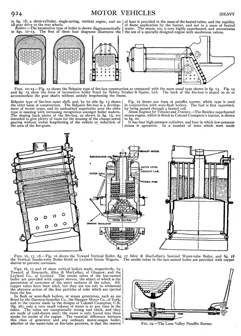
Boilers.—The locomotive type of boiler is shown diagrammatically in figs. 12–15. The first of these four diagrams illustrates the Belpaire type of fire-box outer shell, and, by its side fig. 13 shows the older form of construction. The Belpaire fire-box is a development of recent years, and its undoubted superiority over the older type is meeting with increasing recognition amongst boiler makers. The sloping back plates of the fire-box, as shown in fig. 15, are intended to give plenty of room for the housing of the change-speed gearing without undue lengthening of the vehicle or reduction of the area of the fire-grate.
| Figs. 16, 17, 18.—Fig. 16 shows the Toward Vertical Boiler, fig. 17 Alley & MacLellan’s Sentinel Water-tube Boiler, and fig. 18 the Vertical Smoke-tube Boiler fitted on Leyland Steam Wagons. The smoke tubes in the last-named boiler are provided with copper sleeves to prevent corrosion. |
Figs. 16, 17 and 18 show vertical boilers made, respectively, by Toward, of Newcastle, Alley & MacLellan, of Glasgow, and the Leyland Co., of Leyland. The smoke tubes of the last-named boiler are provided with copper sleeves, the object of which is the prevention of corrosion of the outer surfaces of the tubes. All-copper tubes have been tried, but they are too soft to withstand the abrasive action of the fine particles of coke which are ejected from the fire.
In flash or semi-flash boilers, or steam generators, such as are fitted by the Darracq-Serpollet Co., the Sheppee Motor Co., of York, and to the tractor made to the designs of Colonel Crompton, C.B. (fig. 26), only a very small volume of water is at any time in the tubes. The tubes are exceptionally strong and thick, and, they are made of cold-drawn steel; the water is only forced into them stroke for stroke of the engine. The essential difference between this class of generator and any ordinary motor-wagon boiler, whether of the water-tube or fire-tube patterns, is that the reserve of heat is provided in the mass of the heated tubes, and the rapidity of flame application by the burner, and not in a mass of heated water. The steam, too, is very highly superheated, and necessitates the use of a specially-designed engine with mushroom valves.
Fig. 19 shows one form of paraffin burner, which type is used in conjunction with semi-flash boilers. The fuel is first vaporized, by being passed through a heated coil.
Fig. 19.—The Lune Valley Paraffin Burner.
Steam Engines for Vehicles and Tractors.—The Bentley superheated steam engine, which is fitted to Colonel Crompton’s tractor, is shown in fig. 20.
It has four high-pressure cylinders, and four in which low-pressure steam is operative. In a number of tests which were made with an engine of this type it was found possible to work it on an expenditure of 13 ℔ of water per brake-horse-power hour.
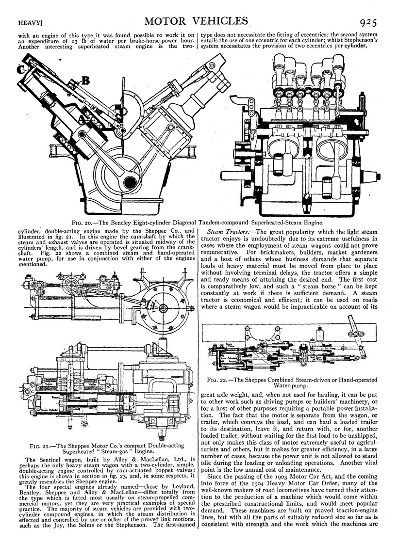
Fig. 20.—The Bentley Eight-cylinder Diagonal Tandem-compound Superheated-Steam Engine.
Another interesting superheated steam engine is the two-cylinder, double-acting engine made by the Sheppee Co., and illustrated in fig. 21. In this engine the cam-shaft by which the steam and exhaust valves are operated is situated midway of the cylinders’ length, and is driven by bevel gearing from the crank-shaft. Fig. 22 shows a combined steam and hand-operated water pump, for use in conjunction with either of the engines mentioned.
Fig. 21.—The Sheppee Motor Co.’s compact Double-acting
Superheated “Steam-gas” Engine.
The Sentinel wagon, built by Alley & MacLellan, Ltd., is perhaps the only heavy steam wagon with a two-cylinder, simple, double-acting engine controlled by cam-actuated poppet valves; this engine is shown in section in fig. 23, and, in some respects, it greatly resembles the Sheppee engine.
The four special engines already named—those by Leyland, Bentley, Sheppee and Alley & MacLellan—differ totally from the type which is fitted most usually on steam-propelled commercial motors, yet they are very practical examples of special practice. The majority of steam vehicles are provided with two-cylinder compound engines, in which the steam distribution is effected and controlled by one or other of the proved link motions, such as the joy, the Solms or the Stephenson. The first-named type does not necessitate the fitting of eccentrics; the second system entails the use of one eccentric for each cylinder; whilst Stephenson’s system necessitates the provision of two eccentrics per cylinder.
Fig. 22.—The Sheppee Combined Steam-driven or Hand-operated Water-pump.
Steam Tractors.—The great popularity which the light steam tractor enjoys is undoubtedly due to its extreme usefulness in cases where the employment of steam wagons could not prove remunerative. For brickmakers, builders, market gardeners and a host of others whose business demands that separate loads of heavy material must be moved from place to place without involving terminal delays, the tractor offers a simple and ready means of attaining the desired end. The first cost is comparatively low, and such a “steam horse” can be kept constantly at work if there is sufficient demand. A steam tractor is economical and efficient; it can be used on roads where a steam wagon would be impracticable on account of its great axle weight, and, when not used for hauling, it can be put to other work such as driving pumps or builders’ machinery, or for a host of other purposes requiring a portable power installation. The fact that the motor is separate from the wagon, or trailer, which conveys the load, and can haul a loaded trailer to its destination, leave it, and return with, or for, another loaded trailer, without waiting for the first load to be unshipped, not only makes this class of motor extremely useful to agriculturists and others, but it makes for greater efficiency, in a large number of cases, because the power unit is not allowed to stand idle during the loading or unloading operations. Another vital point is the low annual cost of maintenance.
Since the passing of the 1903 Motor Car Act, and the coming into force of the 1904 Heavy Motor Car Order, many of the well-known makers of road locomotives have turned their attention to the production of a machine which would come within the prescribed constructional limits, and would meet popular demand. These machines are built on proved traction-engine lines, but with all the parts of suitably reduced size so far as is consistent with strength and the work which the machines are called upon to perform. The locomotive type of boiler, with large fire-box, a heating surface of about 65 sq. ft., and a grate area of some 3 sq. ft., is used by the leading makers.
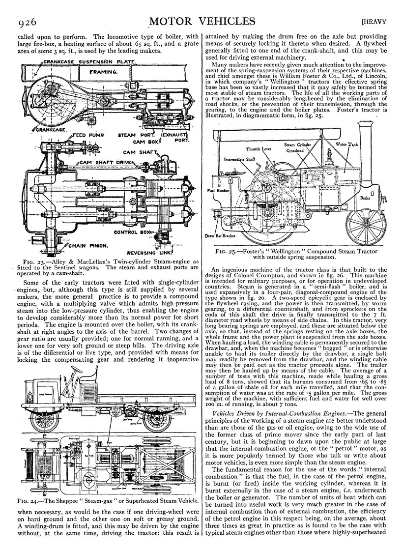
Fig. 23.—Alley & MacLellan’s Twin-cylinder Steam-engine as fitted to the
Sentinel wagons. The steam and exhaust ports are operated by a cam-shaft.
Some of the early tractors were fitted with single-cylinder engines, but, although this type is still supplied by several makers, the more general practice is to provide a compound engine, with a multiplying valve which admits high-pressure steam into the low-pressure cylinder, thus enabling the engine to develop considerably more than its normal power for short periods. The engine is mounted over the boiler, with its crank-shaft at right angles to the axis of the barrel. Two changes of gear ratio are usually provided; one for normal running, and a lower one for very soft ground or steep hills. The driving axle is of the differential or live type, and provided with means for locking the compensating gear and rendering it inoperative
Fig. 24.—The Sheppee “Steam-gas” or Superheated Steam Vehicle.
when necessary, as would be the case if one driving-wheel were on hard ground and the other one on soft or greasy ground. A winding-drum is fitted, and this may be driven by the engine without, at the same time, driving the tractor: this result is, attained by making the drum free on the axle but providing means of securely locking it thereto when desired. A flywheel generally fitted to one end of the crank-shaft, and this may be used for driving external machinery.
Many makers have recently given much attention to the improvement of the spring-suspension systems of their respective machines, and chief amongst these is William Foster & Co., Ltd., of Lincoln, in which company’s “Wellington” tractors the effective spring base has been so vastly increased that it may safely be termed the most stable of steam tractors. The life of all the working parts of a tractor may be considerably lengthened by the elimination of road shocks, or the prevention of their transmission, through the gearing, to the engine and the boiler plates. Foster’s tractor is illustrated, in diagrammatic form, in fig. 25.
Fig. 25.—Foster’s “Wellington” Compound Steam Tractor with outside spring suspension.
An ingenious machine of the tractor class is that built to the designs of Colonel Crompton, and shown in fig. 26. This machine is intended for military purposes, or for operation in undeveloped countries. Steam is generated in a “semi-flash” boiler, and is used expansively in a four-pair, diagonal-compound engine of the type shown in fig. 20. A two-speed epicyclic gear is enclosed by the flywheel casing, and the power is then transmitted, by Worm gearing, to a differential countershaft, and from sprockets on the ends of this shaft the drive is finally transmitted to the 7 ft. diameter road wheels by means of side chains. In this tractor, very long bearing springs are employed, and these are situated below the axle, so that, instead of the springs resting on the axle boxes, the whole frame and the power plant is suspended from the axle boxes. When hauling a load, the winding cable is permanently secured to the drawbar, and, when the machine becomes “bogged” or is otherwise unable to haul its trailer directly by the drawbar, a single bolt may readily be removed from the drawbar, and the winding cable may then be paid out as the tractor proceeds alone. The trailer may then be hauled up by means of the cable. The average of a number of tests with this machine, made while hauling a gross load of 8 tons, showed that its burners consumed from ·65 to ·85 of a gallon of shale oil for each mile travelled, and that the consumption of water was at the rate of ·5 gallon per mile. The gross weight of the machine, with sufficient fuel and water for well over 100 m. of running, is about 7 tons.
Vehicles Driven by Internal-Combustion Engines.—The general principles of the Working of a steam engine are better understood than are those of the gas or oil engine, owing to the wide use of the former class of prime mover since the early part of last century, but it is beginning to dawn upon the public at large that the internal-combustion engine, or the “petrol” motor, as it is more popularly termed by those who talk or write about motor vehicles, is even more simple than the steam engine.
The fundamental reason for the use of the words “internal combustion” is that the fuel, in the case of the petrol engine, is burnt (or fired) inside the working cylinder, whereas it is burnt externally in the case of a steam engine, i.e. underneath the boiler or generator. The number of units of heat which can be turned into useful work is very much greater in the case of internal combustion than of external combustion, the efficiency of the petrol engine in this respect being, on the average, about three times as great in practice as is found to be the case with typical steam engines other than those where highly-superheated steam is used, and where the whole of the parts are maintained in the best condition. The amount of petroleum spirit, or of paraffin, required to propel a steam vehicle 1 m. would, other conditions being equal, propel a vehicle fitted with an internal-combustion engine over a distance of 3 m.
The essential parts of any internal-combustion system are: the carburetter; the engine; the radiator; the clutch; the change-speed gears and the final transmission. The carburetter is a vessel in which the liquid fuel is converted into a combustible gas or Vapour, for, as there is no Connexion to any gas main, the ordinary petrol engine has to make its gas “on the premises.” The production of the gas is automatic, and calls for practically no attention from the driver, because, once the engine is started, the necessary aspiration to draw through the correct quantities of air and fuel is provided by the action of the valves and pistons.
A smart turn of the starting handle is required to set the pistons and crankshaft in motion, so that an initial supply of the combustible mixture may reach one of the cylinders. This first charge of gas is automatically ignited by an electric spark, the current for which is furnished and controlled without the necessity for any hand regulation, and there is then nothing further for the driver to do, as regards power, except to move a convenient lever which opens or closes a “throttle” valve between the cylinders and the carburetter.

Fig. 26.—Colonel Crompton’s Superheated Steam Tractor.
An internal-combustion engine would get very hot if no precaution were taken to cool it, and it is usual to surround the cylinder with water spaces. These spaces are called jackets, and the water is forced through them, either by a pump or by thermo-siphon (natural circulation) action. It is expedient to keep down the weight of water, and for that reason pipes, tubes or small boxes are built up in such a manner that a large cooling surface is exposed to the air. A fan, which is driven from the crankshaft of the engine by gear or a belt, is employed to aid this cooling by reason of the increased volume of air that passes round the outside of the components of the radiator members. The general scheme is the same, both for heavy and light motor-cars.
It is very important that the driver should have a convenient means of separating the engine from the driving mechanism, and of putting the two in connexion again, whenever it becomes necessary, without jar or shock. The common practice is to use a leather-faced, circular member with a coned face, and to control the amount of “grip” between this member and a corresponding enclosing member attached to the engine flywheel by means of a pedal and springs. When the driver wishes to disengage the two members, he has merely to depress the foot lever. It will be clear that a clutch of this description can be made to engage without any difficulty, there being no fixed positions or steps such as one associates with the ordinary jaw-clutch, and this gradual application of the load can only be accomplished by the aid of two or more surfaces in frictional contact, and by the holding together of these surfaces by the pressure of one or more strong springs. The Hele-Shaw multiple-disk clutch gives very good results, and is easy for drivers to use in traffic.
Fig. 27.—The well-known 16 h.p. Two-ton Albion Chassis.
An internal-combustion engine cannot develop power unless the crank-shaft can rotate at a relatively high number of revolutions, and the rate of doing work is lowest when the angular velocity is at its minimum. It is, therefore, necessary to introduce a system of levers between the engine and the road wheels, in order to permit the number of revolutions of the crankshaft to be maintained when hill climbing, or when the vehicle is carrying a heavy load, and the common practice is to introduce three or four sets of different sizes of toothed wheels, any pair of which can be put into engagement by the movement of a single lever, which lever is placed near the driver’s right hand as a rule. The lowest of these gear ratios, i.e. the one which allows the crankshaft to make the greatest number of revolutions to one revolution of the road wheels, is required for starting purposes, and the highest gear ratio, i.e. the one which allows the road wheels to make the greatest number of revolutions in relation to those of the crankshaft, is employed for high-speed travelling on the road. From the last change-speed shaft the power must be transmitted to the road wheels through a differential gear and through one or other of the types of final drive which are now employed by representative makers. The great distinction from the axle of a horse-drawn vehicle is that there must be both a mechanical connexion, yet a differential action, between the two back wheels. The wheels on horse vehicles revolve loosely on the axle, and one can overrun the other at curves, but the special device known as the “differential gear” has to be introduced into all motor vehicles between the change-speed gears and the driven road wheels. Such a device permits one of the two driving wheels to be driven round at a quicker angular speed than the other, the difference being determined by the radius of the curve around which the vehicle is turning.
Fig. 28.—Halley’s Van or Lorry Chassis with 20 h.p. Engine.
The most common form of final drive is, perhaps, that in which two “roller” or “silent” chains transmit the power from sprockets on the ends of the differential shaft to chain rings which are bolted to the rear road wheels. Figs. 27, 28 and 29 show typical vehicles, ranging in load capacity from 30 cwt. to 6 tons, on which the side-chain method of final drive is adopted. One of the chief advantages of the side-chain drive lies in the fact that there is, with it, less weight below the springs than with any other form of final drive. The only parts below the springs are: the fixed back axle; the chain rings (bolted to the road increased efficiency, on account of the ease with which all the parts can be enclosed in an oil-tight casing. It also gives silence of running. The strongest advocate of the worm drive for heavy vehicles is the Guildford manufa.cturer, Dennis Bros., Ltd., one of which company's machines is illustrated in fig. 31. Although there are many difficulties in the matter of the manufacture of worm gearing, they are not insurmountable, and, given proper attention at the hands of the designer, followed by wheels); the road wheels themselves; the road-wheel brakes and part of the weight of the chains. The differential gear and chain sprockets are carried in a countershaft casing, which is securely bolted to the main frame.

Fig. 29.—A typical Six-ton Petrol Wagon Chassis, by Commercial Cars, Ltd., Luton.
In a number of very successful vehicles the final drive is transmitted by means of spur pinions. These are mounted on the ends of bevel-driven differential shaft, and mesh with internally toothed or externally-toothed gear rings on the road wheels. Milnes-Daimler and De Dion commercial vehicles are amongst the machines on which the internally-toothed form of gear is employed, whilst Ryknield is the most representative vehicle embodying the externally-toothed form of final drive. The direct drive, from the ends of the differential shaft, as is shown in fig. 30, is another type of final transmission that has met with a considerable amount of success, particularly on the Leyland machines of five-ton and six-ton capacity. The differential gear and the bevel-drive reducing gear are both enclosed within a casing that is bolted to a fixed back axle; the ends of the driving shaft pass through tunnels in the axle body; and claw pieces on the outer ends of the differential shaft engage with similar claws on the road-wheel hubs. The two last-named forms of gear are highly efficient, provided the pitch and shape of the teeth are carefully considered and the designs provide for the encasing of all the pinions and gear rings.
Fig. 30.—The Back Axle of the Leyland Six-ton Petrol Wagon.
The only other type of final drive which is used to any great extent for commercial motors is that which employs a hardened and ground steel worm meshing with a machine-cut phosphor-bronze worm wheel which is bolted to the differential-gear cage of a live back axle. The employment of this type of gear for the final transmission on commercial motors generally leads to accurate workmanship, probably no other mechanical means of transmitting power can approach it for smooth and silent operation.
Fig. 31.—A typical Worm-driven Live-axle Chassis, by Dennis Bros., Ltd., of Guildford.
Both thrust bearings on the worm shaft should be on one side of the worm, to avoid lack of truth in meshing if any heating occurs between the worm and the wheel. There are many examples of the worm drive to be found in London on public-service passenger vehicles, and also on delivery vans. One of the great charms of this type of transmission is that a very large gear reduction may be obtained without making the worm wheel unduly large in diameter; this is an important factor in the design of a back axle, as every inch of road clearance is of value for operating on rough country roads. As a large gear reduction is thus rendered possible on the back axle, it will readily be understood that the change-speed gear-box may be made considerably smaller than would be necessary for a bevel-driven live axle, where a large gear reduction is not permissible, both on account of its size and because such a gear would be very noisy in its working.
Fig. 32.—The Hallford-Stevens Petrol-electric Chassis.
Although the use of tooth wheels is still the only practical method of obtaining variable transmission for motor vehicles, the fundamental defects of transmission in this way are inherent to the system and must always be present; they are now less apparent, thanks to the remarkable improvement which has taken place in the use of suitable materials and improved design.

Fig. 33.—70 h.p. Six-cylinder Dennis Fire-engine with Gwynne Centrifugal Pump.
Fig. 34.—60 h.p. Six-cylinder Halley Fire-engine with Centrifugal Pump.
Fig. 35.—One of Barford & Perkins’s Water-ballast Rollers.
It is still the hope of some manufacturers that a form of infinitely variable change-speed device will be produced, which will replace the step-by-step movement of toothed gearing; the two chief directions in which this has been attempted are electrical and hydraulic. Of these two, electrical devices are really step by step, and the hydraulic method is apparently the only one that permits of infinite variation. Enormous sums of money have been spent in the search for an effective hydraulic gear; the work of Hall, Pittler, Jannay, Hele-Shaw, Renault and others is, perhaps, the best known. It must be confessed, however, that in 1910 none of these gears could be said to be on the market for motor vehicles, although hydraulic gears were being successfully applied in connexion with other problems, such as the steering of ships, the movement of turrets, &c.
Fig. 36.—Marshall’s 30 h.p. Agricultural Tractor.
Electrical transmission systems, too, have been tried, and appear to have been attended with more success than those of the hydraulic type. Such systems include Vehicles which carry heavy batteries of accumulators, the current from which is utilized for the driving of the vehicle by means of electric motors. Other variations include the Hallford-Stevens system, shown in fig. 32, in which it may be seen the petrol engine drives a dynamo, and the current is then caused to drive an electric motor at each side of the chassis. Each motor drives one of the back road wheels, through a worm and worm wheel. The changes of vehicle speed are effected by altering the method of grouping the electrical windings of the dynamo and motor field-magnets and armatures. This system of control is known as the series-parallel, and is effected by a single lever, which actuates a mechanical switch, or “controller.”
In one of the most-recently-introduced petrol-electric systems—the “K.P.L.” system, as worked by the Daimler Co., of Coventry—each of the rear road wheels is provided with a separate power unit, consisting of a four-cylinder petrol engine, which is direct coupled to a dynamotor, the armature of the latter being coupled to a worm which meshes with a worm wheel attached to the road wheel. A small electrical storage battery forms part of the system, and this receives the excess of current from the dynamotors when the whole power of the engine is not required for the propulsion of the vehicle. When the machine is being driven up a steep incline, or when it is required to travel in a reverse direction, the battery may be called upon to supply current to the dynamotor, and, in this manner, the power of the engine is augmented by the dynamotors’ working as electric motors.
Still another petrol-electric system is that invented by Mr Thomas. In this system, which is at the same time the simplest and most practical form of petrol-electric transmission, two dynamotors and an epicyclic gear are employed so that the electrical load is at no time greater than one half of the total load; consequently, the risk of a “burn out” of the windings, as the result of sudden and unforeseen periods of overload, is materially minimized.
Special Applications.—Amongst the special applications of the petrol-engined commercial vehicle is the motor fire-engine, which Has brought to the front in this branch several enterprising motor manufacturers, amongst whom Dennis Bros., of Guildford, Halley, of Glasgow, and Leyland, of Preston, are prominent. The general construction of the chassis closely follows the lines of other petrol vehicles of equal load capacity, but the gear-box tail-shaft is prolonged to the after-end of the machine, and is direct-coupled to the rotary member of a multistage centrifugal pump. In the Dennis fire-engine, the vacuum which is necessary in order to lift the water in the suction hose is obtained by means of priming the pump chamber, further assisted by a water ejector and a small water tank which is carried on the machine. This machine is shown in fig. 33, whilst fig. 34 shows the successful motor fire-engine built by Halley’s Industrial Motors, Ltd., of Yoker, Glasgow. In the latter machine, as also in the Leyland and other fire-engines which employ centrifugal pumps, the vacuum is created by means of reciprocating air pumps. These machines have given very satisfactory results in the hands of practical firemasters, in various parts of the United Kingdom and abroad. Merryweather and Shand-Mason, who were formerly builders, of steam fire-engines, now also build petrol-engined machines, these makers favouring reciprocating water pumps.
Other special applications of the internal-combustion motor are for grass mowing and rolling, and for road mending and rolling gravel paths, &c. One of the latter type of machines is shown in fig. 35. In this machine a petrol or paraffin engine drives a water-ballast roller through the medium of a clutch, a simple form of change-speed gear-box, and a single roller chain.
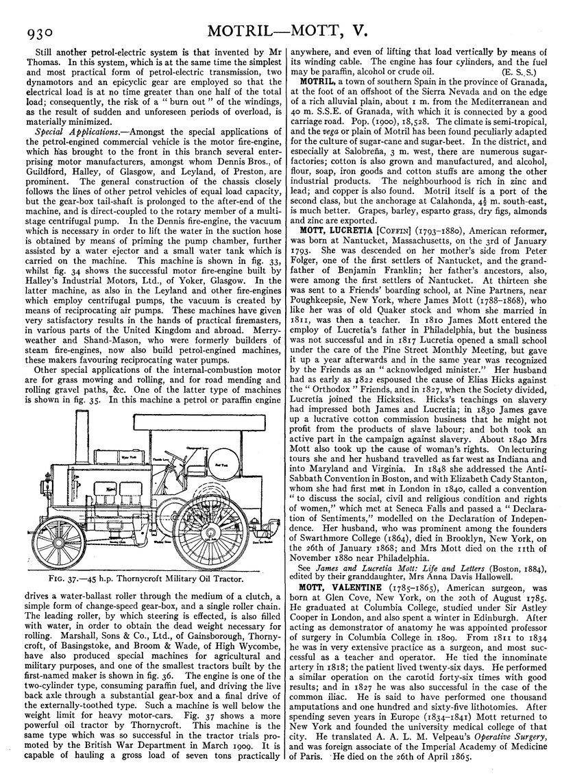
Fig. 37.—45 h.p. Thornycroft Military Oil Tractor.
The leading roller, by which steering is effected, is also filled with water, in order to obtain the dead weight necessary for rolling. Marshall, Sons & Co., Ltd., of Gainsborough, Thornycroft, of Basingstoke, and Broom & Wade, of High Wycombe, have also produced special machines for agricultural and military purposes, and one of the smallest tractors built by the first-named maker is shown in fig. 36. The engine is one of the two-cylinder type, consuming paraffin fuel, and driving the live back axle through a substantial gear-box and a final drive of the externally-toothed type. Such a machine is well below the weight limit for heavy motor-cars. Fig. 37 shows a more powerful oil tractor by Thornycroft. This machine is the same type which was so successful in the tractor trials promoted by the British War Department in March 1909. It is capable of hauling a gross load of seven tons practically anywhere, and even of lifting that load vertically by means of its winding cable. The engine has four cylinders, and the fuel may be paraffin, alcohol or crude oil. (E. S. S.)