elasticity, a radius CD turns round to CD', and a line AD drawn at any distance r froin the axis, and originally straight, changes into the helix AD'. Let be the angle which this helix makes with lines parallel to the axis, or in other words the angle of shear at the distance
Fig. 39.
r from the axis, and let i be the angle of twist DCD'. Taking two
sections at a distance dx from one another, we have^ the arc
Odx = rdi. Hence q, the intensity of shearing stress in a plane of
cross-section, varies as r, since q = C0 = Cr di/dx. The resultant
moment of the whole shearing stress on each plane of cross-section
is equal to the twisting moment M. Thus
J2xr 2 gdr = M. Calling ri the outside radius (where the shearing stress is greatest) and 91 its intensity there, we have g = rgi/n, and hence, for a solid shaft, Si = 2M/nTi s . For a hollow shaft with a central hole of radius U the same reasoning applies : the limits of integration are now n and ri, and
2Mn 91 -*<n« -ftf)- The lines of principal stress are obviously helices inclined at 45 to the axis.
If the shaft has any other form of section than a solid or sym- metrical hollow circle, an originally straight radial line becomes warped when the shaft is twisted, and the shearing stress is no longer proportional to the distance from the axis. The twisting of shafts of square,- triangular and other sections has been investigated by Saint- Venant. In a square shaft (side = Js) the stress is greatest at the middle of each side, and its intensity there is g, = M/o-28ifc 3 .
For round sections the angle of twist per unit of length is
in hollow shafts.
Oi 2M . ... . 2M
- = cV, = 7U;* m solld and «C<r,«-fi«)
In what has been said above it is assumed that the stress is within the limit of elasticity. When the twisting couple is increased so that this limit is passed, plastic yielding begins in the outermost layer, and a larger proportion of the whole stress falls to be borne by layers nearer the centre. The case is similar to that of a beam bent beyond the elastic limit, described above. If we sup- pose the process of twisting to be continued, and that after passing the limit of elasticity the material is capable of much distortion without further increase of shearing stress, the distribution of stress on any cross section will finally have an approximately uniform value q', and the moment of torsion will be
f r i l 2*r>q'dr = WW-ri i ).
In the case of a solid shaft this gives for M a value greater than it has when the stress in the outermost layer only reaches the intensity g', in the ratio of 4 to 3. It is obvious from this consideration that the ultimate strength of a shaft to resist torsion is no more deducible from a knowledge of the ultimate shearing strength of the material than the ultimate strength of a beam to resist bending is deducible from a knowledge of the tensile and crushing strength. It should be noticed also that as regards ultimate strength a solid shaft has an important advantage over a hollow shaft of the same elastic strength, or a hollow shaft so proportioned that the greatest working intensity of stress is the same as in the solid shaft.
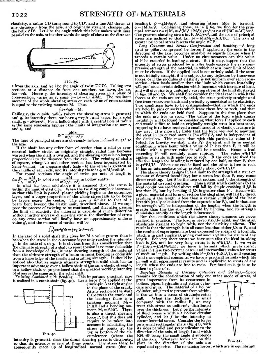
Twisting Combined with Bending. — This important practical case is realized in a crank-shaft (fig. 40). Let a force P be applied at the
crank-pin A at right angles to the plane of the crank. At any section of the shaft C (between the crank and the bearing) there is a twisting moment Mi = P. AB and a bending mo- ment M 2 = P.BC. There is also a direct shearing force P, but this does not _ require to be taken into account in calculating the stress at points at the top or bottom of the circumference (where the intensity is greatest), since the direct shearing stress is distributed
An image should appear at this position in the text. To use the entire page scan as a placeholder, edit this page and replace "{{missing image}}" with "{{raw image|EB1911 - Volume 25.djvu/1048}}". Otherwise, if you are able to provide the image then please do so. For guidance, see Wikisource:Image guidelines and Help:Adding images. |
so that its intensity is zero at these points. The stress there is consequently made up of longitudinal normal stress (due to bending), pt =4M 2 /irri 3 , and shearing stress (due to torsion), gi = 2Mi/xn 3 . Combining these, as in § 64, we find for the prin- cipal stresses r = 2JM 8 ±V(Mi 2 -r-M s 2 )}/irri 3 ,orr = 2P(BC±AC)/irn 3 . The greatest shearing stress is2P. ACjirri 3 , and the axes of principal stress are inclined so that tan 20 =Mi/M 2 = AB/BC. The axis of greater principal stress bisects the angle ACB.
Long Columns and Struts : Compression and Bending. — A long strut or pillar, compressed by forces P applied at the ends in the direction of the axis, becomes unstable as regards flexure when P exceeds a certain value. Under no circumstances can this value of P be exceeded in loading a strut. But it may happen that the intensity of stress produced by smaller loads exceeds the safe com- pressive strength of the material, in which case a lower limit of load must be chosen. If the applied load is not strictly axial, if the strut is not initially straight, if it is subject to any deflexion by transverse forces, or if the modulus of elasticity is not uniform over each cross- section — then loads smaller than the limit which causes instability will produce a certain deflexion which increases with increase of load, and will give rise to a uniformly varying stress of the kind illustrated in figs. 28 and 30. We shall first consider the ideal case in which the forces at the ends are strictly axial, the strut perfectly straight and free from transverse loads and perfectly symmetrical as to elasticity. Two conditions have to be distinguished — that in which the ends are held by pins or sockets which leave them free to rock, and that in which the ends are held fixed. Suppose in the first place that the ends are free to rock. The value of the load which causes instability will be found by considering what force P applied to each end would suffice to hold an originally straight strut in a bent state, supposing it to have received a small amount of elastic curvature in any way. It is shown by Euler that the force required to maintain the strut in its curved state is P=ir s EI/L 2 , and is independent of the deflexion. This means that with this particular value of P (which for brevity we shall write Pi) the strut will be in neutral equilibrium when bent; with a value of P less than Pi it will be stable; with a greater value it will be unstable. Hence a load exceeding Pi will certainly cause rupture. The value 7r 2 EI/L 2 applies to struts with ends free to rock. If the ends are fixed the effective length for bending is reduced by one half, so that Pi then is 4«^EI/L 2 . When one end is fixed and the other is free to rock Pi has an intermediate value, probably about 9VEI/4L 2 .
The above theory assigns Pi as a limit to. the strength of a strut on account of flexural instability; but a stress less than Pi may cause direct Crushing. Let S be the area of section, and f c the strength of the material to resist crushing. Thus a strut which conforms to the ideal conditions specified above will fail by simple crushing if / e S is less than P^ but by bending if f c S is greater than Pi. Hence with a given material and form of section the ideal strut will fail by direct crushing if the length is less than a certain multiple of the least breadth (easily calculated from the expression for Pi) , and in that case its strength will be independent of the length ; when the length is greater than this the strut will yield by bending, and its strength diminishes rapidly as the length is increased.
But the conditions which the above theory assumes are never realized in practice. The load is never strictly axial, nor the strut absolutely straight to begin with* nor the elasticity uniform. The result is that the strength is in all cases less than either / C S or Pi, and the results of experiments are best expressed by means of a formula, which is in part empirical, giving continuous values for struts of any length. For very short struts we have seen that the ideal breaking load is fjS, and for Very long struts it is ir 2 EI/L 2 . If we write P=/ e S/(i+/cSL 2 /ir 2 EI), we have a formula which gives correct values in these two extreme cases, and intermediate values for struts of medium length. By writing this P=/S/(i-fcSL 2 /I), and treating /and c as empirical constants, we have a practical formula which fits in well with experimental results and is applicable to struts of any length when the ends are free to rock. For fixed ends \c is to be taken in place of e.
Bursting Strength of Circular Cylinders and Spheres. — Space remains for the consideration of only one other mode of stress, of great importance from its occurrence in T T
boilers, pipes, hydraulic and steam cylin- '
ders and guns. The material of a hollow cylinder, subjected to pressure from within, is thrown into a stress of circumferential pull. When the thickness t is small compared with the radius R, we may treat this stress as uniformly distributed over the thickness. Let p be the intensity of fluid pressure within a hollow circular cylinder, and let / be the intensity of circumferential stress. Consider the forces on a small rectangular plate (fig. 41), with its sides parallel and perpendicular to the direction of the axis, of length / and width R50, 89 being the small angle it.subtends at the axis. Whatever forces act on this plate in the direction of the axis are equal and opposite. The remaining forces, which are in equilibrium,