GLAM/Newsletter/April 2022/Single
Growing the record of Australian Music

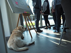
While Melbourne is often thought of as Australia’s music capital, many of Australia’s best bands originated 70 kilometres south west, in the city of Geelong. So in April, Wikimedia Australia held an edit-a-thon at Geelong Library & Heritage Centre to create and expand Wikipedia pages about Geelong’s musicians.
The event was held as part of Surround Sounds, a new local arts festival in Geelong, and was supported by The Australian Music Vault and the Geelong Library & Heritage Centre.
Wikimedia Australia's James Gaunt and Alex Lum supported nearly a dozen participants to get acquainted with the ins and outs of editing Wikipedia and Wikimedia Commons.

Participants came from a variety of backgrounds, including musicians, radio presenters, authors, and journalists, as well as music fans and collectors. Many said they had always wanted to know how to edit and add pages to Wikipedia, with ambitions to work together to collect local regional knowledge to be added to Wikipedia in the months to come.
This event was part of a new Australian Music Project called 'The Record' launched with founding partner the Australia Council for the Arts in December 2021. It set out the create or expand 50 Wikipedia pages at four edit-a-thons by the end of June 2022. These in-person and online edit-a-thons held in partnership with the Australian Music Vault, Australian Music Centre, Country Music Association of Australia, and APRA AMCOS, have generated 46 new pages, with just under 30 existing pages expanded with new references and information.
Each of the events has had a special guest, and in Geelong Maree Robertson joined us to talk about her new book Bored! This Was Geelong and discuss her passion for writing about Geelong’s music history. At the end of our edit-a-thon we also joined Maree at a local gallery where photographs from her book were being exhibited.
With one remaining edit-a-thon focused on First Nations artists, the project has generated widespread interest from across the music industry in Australia. Whether its music organisations, festivals, or fans, there has been a massive outpouring of support around the idea of getting more Australian music content online.
Read more about The Record here.
About African Pagnes and Belgian music
African pagnes in the Museum of Industry (Ghent)

The Museum of Industry (Ghent) organises a temporary exhibition on African pagnes until June 7, 2022. Several historical Ghent textile factories produced cotton textile for, and in Belgian Congo. On May 5th a writing session was held about Pagne Africain.
Ghent Conservatory
Article about Palmyre Buyst in Russian
A photo about Palmyre was uploaded during the writing session on March 25, 2022. The picture was linked to Wikidata and automatically appeared on the Russian Wikipedia, thanks to reusing Wikidata statements from an infobox.
Two lectures in the Music Library
On May 19 and June 2, 2022 the Muziekbibliotheek Gent will hold two lectures. These presentations will be in English and are free and open to the public.
- May 19, 19.00h, Muziekbibliotheek Gent
Ellie Nimeroski - François Xavier Tourte and L'Archet de Viotti: Perspectives from a Violinist at the Workbench.
- June 2, 19.00h, Muziekbibliotheek Gent
Peter François - François Servais: The Paganini of the cello and the Belgian School of cello playing.
Brazil wins the first place in WLM 2021

The winning picture of Wiki Loves Monuments 2021 was taken inside the Royal Portuguese Cabinet of Reading, a cultural institution located in Rio de Janeiro. Elected the fourth most beautiful library in the world by Time Magazine, this Neo-Manueline style building was designed by the Portuguese architect Rafael da Silva e Castro and built between 1880 and 1887. The winning picture shows the reading room where part of the largest Portuguese collection outside Portugal is available for consultation: around 300,000 volumes of national and foreign works. It is the first time an image from Brazil wins the global Wikimedia competition.
The photographer is Donatas Dabravolskas, who is originally from Lithuania and has lived in Brazil since 2013. According to him, in a recent interview:
| “ | This place is located at a fifteen-minute walking distance from my house. By chance I saw some pictures on social media, some bloggers posts, etc. I thought: what a nice place! So I looked for its location because I wanted to get there and take some pics. And when I realized it was near my house, I thought to myself: I have to go there! | ” |
The WLM winning photo was taken in 2018. Donatas went there many times because he wanted to “capture everything that was possible from that place”, as he said. So the 2021 WLM list was published and he had no doubt: “when I saw this library on the list of monuments for the contest, I decided to send them all. I sent several photos of this monument [to Wikimedia Commons]”.
After the announcement of the result of WLM 2021 on April 19th, Donatas couldn't hide his happiness with the national and international recognition of his work: “This is the best thing: I’m recognized for something I like to do”.
For the first time in eleven years of WLM, a picture outside Europe and Asia won the first place in the competition. This picture was selected among the 172,666 photos submitted to the international final round in 2021.
We hope you enjoy all the pics taken by Donatas and also encourage you to send your own ones for the competition in 2022.
And remember: All the wonderful photos sent to this 12th edition of the competition are now part of Wikimedia Commons and can be consulted and used by anyone!
Brazilian plans for WLM 2022
Wiki Movimento Brasil (WMB) is working on some improvements for this year's competition:
- Improvement in UX with a dedicated app for map visualization and media upload, especially conceived for mobile-phone users;
- Addition of more monuments to the lists aiming to improve coverage of all the Brazilian states and state capitals, which leads to increased diversity in contributions;
- Campaigns to encourage participants to send photos of different types and perspectives, with the purpose of improving the representation of the monuments on Wikidata with more properties being filled; and
- This year, there will be a special prize for photographs of the state of Espírito Santo monuments.
Wiki Loves Espírito Santo
As you may know every year WMB wants to reduce the information gap about one of the Brazilian States. Last year, Bahia was the star of our first edition (see more in Wiki Loves Bahia). Between July and November 2021, we held five edit-a-thons that brought together 161 participants, who edited 1,257 articles on Wikipedia in Portuguese and created another 298 new ones.
Now it’s time for a new challenge: Espírito Santo! This is a Brazilian SouthWest State and it’s still really underrepresented in Wiki: 79% of its 250 monuments have no picture.


A special partnership
And we are happy to announce that now our source of listed monuments in Brazil is turning into a WikiProject!
iPatrimônio is a volunteer project held by three professionals from different and complementary fields of knowledge. Caio Lucena, the creator of the project, is an Electrical Engineer; Cida Barros, the Social Media Manager, is a journalist specialized in social media; and I, the “search-organize-and-complement-information bot”, am Advertiser and Architect.
This partnership aims to enlarge even more the number of monuments in this year’s WLM monuments list. And we hope it may last many years.
French GLAM meeting
French GLAM meeting

Several round tables allowed us to understand the state of play, the constraints and the opportunities offered by open content policies to GLAMs.
Despite the fact that the event was only offered in IRL, different regions of France were represented.
An assessment of the meeting will be made soon.
-
 Round table about French open content report
 -
 GLAM attendees
 -
 INHA auditorium
 -
 Open content report
 -
 Glamers networking


Work with GLAMs on Wikisource and Wikimedia Commons
Listening to classical music on Wikisource
_-_Archivio_storico_Ricordi_FOTO000757_B.jpg)
Thanks to the collaboration between Wikimedia Italia and Archivio Ricordi, it's now possible to listen to music on Wikisource; the work was conducted with the help of a Wikimedian in residence, musician (composer, teacher, instrumentalist) and IT, supporter of free software. For some time now, Archivio Ricordi has been making online digital reproductions of its music magazines. In recent months, the archive has welcomed Wikimedia Italia’s proposal to experiment with the use of free LilyPond software to transcribe music scores.
Being able to listen to music on Wikisource is in fact a fairly new experience for this project. Now in the Wikisource pages where the transcribed scores are present it is possible not only to read the music, but also to listen to it directly. Some of these pieces were not performed until the time of their publication, between the nineteenth and the very first years of the twentieth century.
Some results here:
- Una sonata da camera del Settecento
- “Fantasia”, “Osanna” dalla Messa Benedicta es cælorum regina (Cristóbal de Morales), e Fantasia n. 5 (Francesco da Milano)
Wikimedia Italia goes to Calabria

Calabria, an italian region in Southern Italy, has a great historical and artistic heritage, still little documented on Wikimedia projects. For this reason, from April 30 to the 1st of May, some staff members, board members and volunteers of Wikimedia and OpenStreetMap projects took part in a trip (called Wikigita: wiki + trip) to work to increase the content related to Calabria available on collaborative projects. The starting point was the documentation of the cultural heritage of the region.
The trip included a preparatory phase to identify the assets and study the missing documentation; an on-site itinerary to document the cultural heritage with photographs (which will be uploaded in September to contribute to Wiki Loves Monuments) and a series of meetings to facilitate the planning of Wiki Loves Calabria as a local competition of Wiki Loves Monuments 2022.
GLAM professionals add an image and become Wikipedians; Edificio Carolino Edit-a-thon
Inviting new editors, one image at a time
On April 1, we joined forces with Wikimedia Argentina and Wikimedia Chile to bring Wikipedia to GLAM professionals new to Wikipedia/media.
The WMF's Growth Team has been working on many tools to aid newcomers, so that the technological barrier to editing Wikipedia is as low as possible. One such effort is the tool known as «Add an Image»—still in beta—that aids newcomers make quick and significant edits to images. This tool lists a series of articles without images and a potential image that could improve the article; usually suggested because the metadata matches or is used in the same article in other languages.
We reached out to We reached out to Mexicana—an open repository of Mexican Cultural heritage—and the Secretariat of Culture to help us get the word out: we’ve worked with both institutions before and we knew there’s still more to do. We received over 100 sign-ups 100 sign-ups, coming from various institutions across the country, including:
- UNAM—The National Autonomous University of Mexico and oldest university in the Americas;
- ENCRyM—National School of Conservation, Restoration and Museography;
- ENAH—National School of Anthropology and History;
- Public universities (University of Guadalajara, Autonomous University of Tabasco, Autonomous University of Aguascalientes, Universidad Vizcaya de las Américas)
- Public libraries (National Library of Mexico, Amado Nervo Community Public Library, Prof. Ma. Ignacia Martínez de Loza Community Library, Azcapotzalco Borough, Tulancingo Municipality)
On April 1st, we hosted a virtual meeting in two parts. The first was a short introduction to the WMF's work with GLAM, as well as our work with GLAM institutions. After that Cora Gamarnik, researcher on photojournalism, gave us a lecture on the importance of images and their correct context for academic purposes. The second part of our meeting was spent editing, adding images here and there and learning in general how Wikipedia is made through edits big and small.
In the end, over 30 participants were not just fascinated with Wikipedia and how it works, but eager to learn more beyond the scope of this tool, their inquisitive minds immediately wanted to know how to upload more images, how to improve the articles' text, how were articles sourced and most everything that had to do with helping us through their specialized knowledge.
In sum, we witnessed the birth of Wikipedians. And that is always a marvellous sight to behold.
Edificio Carolino Edit-a-thon
On April 9, Wikimedia Mexico organized the Edificio Carolino Edit-a-thon as a part of activities of the Benemérita Universidad Autónoma de Puebla (BUAP) 35th National Book Fair (FENALI). Our editing session took place at the XVI century Casa de las Bóvedas, an historical building located in the Historic Centre of Puebla.
After two years of being held online due to COVID 19 pandemic, FENALI returns to an in-person format and people from all parts of Mexico attended the event, which offers activities as book sales and presentations, conferences, workshops, karaoke contests, panel discussions and a Wikipedia editing session.
The Historic Centre of Puebla has historical buildings with large doors, balconies, beautiful decorative elements and many years of history. And on this occasion, we wanted to put emphasis on one of its most representative architectural works such as the Edificio Carolino, which today houses the rectory and administrative offices of BUAP; although we also edited about some other notable places such as the Casa del Presidio, the Museo José Luis Bello y Zetina, Museo de Arte Religioso de Santa Mónica, the Casa del Pueblo, Museo Amparo, the Teatro de la Ciudad, the Patio de los Azulejos; and also notable Poblano people like Rosaura Pozos or the Narváez Sisters.
The editing day was very pleasant, as we were able to have backstage access to know some of the properties we were editing and our volunteers could not miss the opportunity to take pictures and release them on Wikimedia Commons to illustrate the articles on Wikipedia. In addition, we were able to attend some FENALI events, chat with local attendees and purchase some books and/or local art pieces.


People in Paleontology, Digikult, and copyright term extension for New Zealand
_04_(cropped).jpg)
People in Paleontology workshop
From March 29–31 New Zealand wikimedian Ambrosia10 participated in and supported the attendees of an iDigBio three day workshop encouraging paleontologists, museum curators and collection managers to add data about people in paleontology to Wikidata. It was an extremely productive workshop with approximately 30 attendees. On the first day Jessica Utrup took the participants through an introduction to editing Wikidata. On the second day Erica Krimmel gave an introduction to the group on how to bulk edit Wikidata via Open Refine. On the third day the group collaborated on creating documentation guidelines for adding paleontology people to Wikidata. The workshop report outlines the outcomes of the gathering and future meetings of the group are anticipated.
Digikult
On the 7th of April Aotearoa New Zealand wikimedian Ambrosia10 presented at Digikult, a Nordic conference on digital cultural heritage. Her presentation entitled "GLAMs and Citizen Science: Encouraging and Enabling Participation" gave recommendations and suggestions to GLAMs on how to encourage citizen scientists to engage and reuse GLAM content and data. During her presentation she highlighted reuse of GLAM content in Wikipedia, Wikidata and Wikimedia commons. Her slides and presentation script can be found at https://doi.org/10.5281/zenodo.6420698.
Submission on copyright term extension
As part of a free trade agreement with the UK, New Zealand negotiators offered to extend our copyright term from 50 years after death to 70 years. A select committee invited submissions on the FTA, and various groups had a chance to make oral presentations over Zoom, including the library professional body LIANZA, and Tohatoha (which advocates for Creative Commons and open knowledge). Giantflightlessbirds also gave a presentation, as a digital librarian in a public library who has been digitising out-of-copyright New Zealand books for Wikisource. As a result of this process several people in the library/copyright space in New Zealand are now discussing how we can raise public awareness of what would be lost by a 20-year term extension; one way would be to start celebrating Public Domain Day, and releasing digitised versions of the complete works of people like Ronald Hugh Morrieson and James K. Baxter (both of whom fall out of copyright in New Zealand next year).
Wikidata for Nigerian Novelist and Novel


Wikidata for Nigerian Novelist and Novel
Wikidata is a free and open knowledge base that serves as a repository for structured data from Wikimedia sister projects such as Wikipedia, Wikivoyage, and Wikisource. It was discovered in a Wikidata query service run before March 2022 that many Nigerian Novels and Novelists were missing from the Wikidata repository, with Zero (https://w.wiki/4nsU) and 38 Novelists (https://w.wiki/4nsS) as a result.
This query resulted in the planning and execution of Wikidata for Nigerian Novelist and Novel by Rhoda James. A campaign to bridge the existing gap by creating and improving Wikidata items for Nigerian novelists and their novels in order to increase visibility for their work on the free data repository.
The physical training sessions were also attended by the Head of Branch National Library of Nigeria Kwara Branch, executive members of the Association of Nigerian Authors Kwara State Chapter, a guest speaker lecturer, Dr. Usman-Oladipo Akanbi (Novelist, and Lecturer at the Department of Agricultural Economics, University of Ilorin; who is also the founder of Imodoye Writers Enclave, Ilorin), and Ma Funmi Omisope (CEO, Home Street Kids Welfare Initiative, Kwara), who shared her experiences as an avid reader with participants at the event. Finally, 10 new editors were recruited, and existing editors' skills were enhanced.
The campaign, which ran from March 10th to May 15th, had over 40 participants on the dashboard and recorded a total of 1.63k items created, 8.45k references added, and 7k item views, as opposed to the initial target of 80 items.
Wikiresidence in progress and workshop Evolution in GLAM in Poland
Wikipedian in residence at the National Library of Poland
-
 Atlas państwa roślinnego : zawierający 125 tablic z 700 rysunkami roślin oraz liczne drzeworyty
 -
 Sacramentarium Tinecense
 -
 Revelationes
 -
 Catalogus archiepiscoporum Gnesnensium
 -
 Irena Krzywicka – Polish feminist, writer, translator, activist for women's rights
.jpg)
_(cropped).jpg)
.jpg)
.jpg)
.jpg)
Polona is the biggest Polish digital library with more than 3,6 mln objects. Since August 2020 around 280 k of files from Polona have been uploaded to Wikimedia Commons by Wikimedian in residence - Redaktor GLAM. The collection includes portraits, archival views of villages and buildings, boards showing fauna and flora, illustrations from books, and manuscripts. It’s the biggest collection uploaded to Wikimedia Commons within GLAM partnerships in Poland. Over 2,6 k files are used at more than 4,7 k Wikimedia pages. Monthly, the average page view number for pages on Wikipedia (and other Wikimedia sites) is more than 1,4 mln.
Although the process of upload is automated thanks to the technical skills of Wikimedian in residence, the most time consuming part where human work needs to be done, is searching and selecting illustrations in a vast collection of Polona. Other responsibilities of Wikimedian in residence at Polona are writing and improving articles connected with the collection, adding external links, adding resources to articles from Polona, illustrating the articles with images from the collection. It is worth noticing that the National Library in Poland mentions in its annual reports the number of visits on its page polona.pl coming from Wikipedia. The latest report (from 2020) states that visits from Wikipedia accounted for 4.39% of all visits (with an absolute increase from 34,902 to 49,320, which is by 41.3%).
Workshop on evolution in GLAM in Poland
-
 Evolution of GLAM in PL workshop
 -
 Evolution of GLAM in PL workshop
 -
 Evolution of GLAM in PL workshop
 -
 Evolution of GLAM in PL workshop


During the Spring Meeting of Polish Wikimedians in Chorzów, the workshop on Evolution in GLAM in Poland was held. The guest of the workshop was Daria Cybulska, Director of Programmes and Evaluation at Wikimedia UK, the co-author of the Wikimedian in Residence Programme Review 2014 and Wikimedians in Residence Impact Report 2012-2017.
The aim of the workshop was to reflect on Polish and British experiences in WIR Programme and open discussion about how we can mutually benefit from sharing knowledge and experience in GLAM. It was a great opportunity to look backwards and discuss how we can improve GLAM residencies in Poland. Further discussion will be continued within the Polish community.
Important activities within the GLAM
Wikipedian in residence at the Serbian Academy of Sciences and Arts
A two-month-long Wikipedian in residence at the Serbian Academy of Sciences and Arts, one of the largest cultural and scientific institutions in Serbia, has ended. During two months of the project, 21 articles were written about its members, 25 were improved, and 80 files were digitized, many of which are bibliographies, as well as video autobiographies, which were released for the first time during this project. This is just the first step in joint activities.
Wikipedian in residence at Ilija M. Kolarac Endowment
A three-month-long Wikipedian in residence at the Ilija M. Kolarac Endowment has ended. As far as 105 articles were illustrated,10 new articles were written, and 527 files were uploaded to Wikimedia Commons. Many of these files have been digitized, and thanks to this project, made available to the public for the first time. Among these files are the will of Ilija Kolarac, programs of performances by many artists, as well as books that introduce us to the art scene in Belgrade during the interwar period.
Training at the National Archives of Sweden; Training at the Stockholm City Museum; Training at the Swedish National Museum of Science and Technology; Improved images from Swedish Performing Arts Agency
Training at the National Archives of Sweden

Staff at the National Archives of Sweden have improved their Wikimedia skills by learning basic editing of Wikipedia, manual uploading of images and editing at Wikimedia Commons and creating objects and adding statements and references at Wikidata. While already contributing various material there are now more staff members (see dashbaord) who can make use of the content, correct typos and errors and connect Q-numbers to make sure the most comes out of all the great images, maps and documents available.
Training at the Stockholm City Museum
As a result of a presentation last fall staff at the Stockholm City Museum hosted a workshop to learn more about Wikipedia and how to edit. During the workshop both the actual editing of Wikimedia projects and the more administrative adding editing to the list of what staff should do was discussed, to make more long term commitment than what can be done in a day. As always the problem is to not only find time to do the one off training but also to find a recurring time in already over crowded calendars.
Training at the Swedish National Museum of Science and Technology
Continuing from the above topics staff at the Swedish National Museum of Science and Technology hosted a training session focusing on adding images from their uploaded collections to articles in different languages. An important reason to make use of the images is the error reports from the community that improves the metadata both on Commons and in the museums own database.
- Gallery added to article about Copenhagen at Danish Wikipedia
-
 Amagertorv, 1901
 -
 Rådhuset, 1901
 -
 Amaliengade, 1904
 -
 Gefionmonumente, 1904


Improved images from Swedish Performing Arts Agency


The Swedish Performing Arts Agency, which houses a large library and archive documenting the history of music and theatre in Sweden, regularly shares the highlights of their collections on Wikimedia Commons. Seeing the files used on the Wikimedia projects, sometimes in unexpected places, is always a joy.
This time, we're excited to see a portrait of Swedish opera singer Lilly Walleni join the over 7 000 featured pictures on English Wikipedia. The photo has been lovingly restored by Adam Cuerden in a process that we can only describe as black magic. Ipigott joined in and wrote up an article about the singer.
The collections of the Swedish Performing Arts Agency on Wikimedia Commons consist of nearly 10 000 images, including many high-resolution archival photographs of prominent actors, singers and dancers. We are happy to see they do not only attract the eyes of Swedish Wikimedians!
Wikidata Coffee Breaks
Wikidata Coffee Breaks
For the first time, Open GLAM Switzerland organized a series of Wikidata Coffe Breaks. In four short 20-minute sessions, newcomers were introduced to Wikidata while more experienced users were given a list of items missing data. With over 200 new properties, mostly coordinates, added to performing arts institutions the project was a success.
Khalili Collections
Khalili Collections

The Talismanic Shirt with Quranic verses was chosen by the English Wikipedia community as Picture Of The Day for 2nd May to celebrate Eid al-Fitr. On the front page for 24 hours, it was potentially seen by 5.1 million viewers. Thousands of extra viewers were attracted to the articles Talismanic shirt, Talisman, and Khalili Collection of Hajj and the Arts of Pilgrimage.
More than three hundred category tags have been added to the Khalili Collections images this month; the images are now visible in more than 1,000 categories. The number of "uncategorised" images went down from 237 to 179. I uploaded two cropped versions of an existing image, one of which is now used to illustrate the Bilal ibn Ribah article. I have been adding images to other articles such as Fairuzabadi, Mary in Islam, and Persian Pottery.
A volunteer has been adding detail to Wikidata about an 11th-century Quran known as the Nurse's Quran. Along with the detail I have been adding, this allows us to create this Wikidata graph showing the four collections that have sections of this manuscript.
I began work on a new article on Islamic enamels, for which the Khalili Collections publications have much more information than presently exists on English Wikipedia.
Wikimedistas de Uruguay report
Workshop with the National Museum of Natural History
As part of ongoing work with the National Museum of Natural History of Uruguay, we held a closed workshop to show them how to edit and discuss next steps for tackling relevant Wikipedia articles for the museum. A picture during the workshop.
Uruguay is part of the International Museum Day
We are taking part on the International Museum Day, organized by Wikimedia Austria. International Museum Day
Environmental issues through the lens of GLAM
As part of the Wiki4HumanRights campaign, we are organizing a round table discussion on "Views from the cultural heritage on the environment and climate change", with panelists from the Wikimedistas Museo de la Plata, the Authority Control of the Riachuelo River of Argentina, and WikiAcción Perú. The talk and the recording will be available on YouTube.
WVU Libraries; Earth Day-2022-SWC; Wiki-Gap
WVU Libraries
WVU Libraries and Art + Feminism held a workshop, Amplifying Appalachia.
Earth Day-2022-SWC
Wikimedia NYC and Sure We Can, held a meetup. Earth Day-2022-SWC
Wiki-Gap
The Embassy of Sweden, Wikimedia NYC, and Wikimedia DC held a meetup, WikiGap/2022/Women, Health & Environment


Open Access vs NFT, GLAM School, Saami language, family trees
AvoinGLAM is a group in Finland that contributes to the global Open GLAM and GLAM-Wiki community. We advocate for open access to cultural heritage and run projects in Finland as well as globally. We have been promoting our backronym for GLAM: Instead of focusing only on institutions with Galleries, Libraries, Archives and Museums, we wish to include the wealth of human and more-than-human cultural heritage by calling it Global Languages, Art & Memory.
Open Access vs NFT

Blog post
In April AvoinGLAM responded to the blog post issued by the Director General of the Finnish National Gallery. In this blog post he argued that the open access policy at the Finnish National Gallery should be replaced by restrictive custom licensing. Our response is based on a collection of reactions of the Open GLAM and GLAM-Wiki proponents in discussions about the blog post. Read AvoinGLAM's response including commentary by the Director General Mr. Kimmo Levä (English, Finnish).
Webinar
Parallel to the response, we arranged a discussion event focusing on Open Access to cultural heritage, monetization, and NFT. The idea of monetizing museum collections by trading on the crypto platforms is a new and surprising idea for the cultural heritage sector. This event allowed us to understand what it is about and to voice concerns that the advocates for open access to cultural heritage have brought up. Read the page that contains the video recording of the discussion and a collection of recommended readings about the topic (English, Finnish).
GLAM School invites participants

In the GLAM School project we are discovering practices that help GLAM professionals, GLAM-Wiki volunteers, Open GLAM advocates and others to be more empowered to contribute to Wikimedia and other open projects. We are conducting surveys, chats, and interviews across organizations and networks to learn about the needs as well as existing resources and practices for learning.
We are inviting you to share your knowledge about learning GLAM practices!
On the GLAM School page, you can book an interview or alternatively fill in the survey in Google Forms or on-wiki. You don't have to share all your thoughts at once. Instead, you can add to your answers until the end of the year. You can also translate the questions to your language. That way the survey can be spread in your local context more easily.
The responses are summarised into recommendations but we also plan not to waste time if there's something that could be done immediately.
AvoinGLAM partners with the National Library of Finland in making available services in Northern Saami
The National Library of Finland received funding from Alfred Kordelin Foundation to improve the availability of Sámi languages and cultural materials on their three services: Finna – the Finnish aggregator of GLAM content will get a Northern Saami interface, Finto – the Finnish Ontology and Thesaurus Service will make available the General Finnish Ontology YSO in Northern Saami and completely on Wikidata, and Kotoistus – the Nothern Saami locales will be updated in the CLDR database. AvoinGLAM contributes by supporting further alignment with Wikidata. Read the press release.
Hack4OpenGLAM

Hack4OpenGLAM is an online co-creation event that has been arranged twice (2020 & 2021) by AvoinGLAM in the international context of the Creative Commons Global Summit, supported by Wikimedia Grants. The event invites creators, thinkers, technologists and advocates of Open Access to cultural heritage to come together and learn, design or create together from open content, with open tools, in open collaboration and for the better of the world.
Since the Creative Commons Global Summit is not taking place this year, we are open to new configurations. As an option we are considering finding new host events. Teaming up with a changing host event would produce new encounters with different communities. Another alternative is to become completely independent, but would we lose the opportunity to bring new people together? In any case, we wish to strengthen the network of fellow events, other likeminded events with whom we can share best practices and create activities together.
In 2021, the theme was Knowledge Equity: Highlighting knowledge of individuals, communities, and cultures who have been left out of the spotlight of history, decolonizing cultural historical collections, and acknowledging responsible ways of sharing information online openly.

Wikidocumentaries ❤️ EntiTree
We will start reporting progress to the Wikidocumentaries project in the AvoinGLAM report. Wikidocumentaries is a website that presents Wikimedia content plus media aggregated from open repositories into a nice reading experience, woven together with the help of linked data from Wikidata. The idea is to turn it into a maker space for citizen historians, an interface for enriching the data in any of the linked projects, and to eventually craft these materials into all kinds of stories. The project has been created at Open Knowledge Finland, and for the time being, it will be adopted by AvoinGLAM.
Wikidocumentaries exists in all languages supported by the Wikimedia projects. You can contribute to the project by translating the interface to your language in TranslateWiki. If the interface does not yet exist in your language, you can still view the content in your language by typing "?language=<yourlanguagecode>" in the end of the url.
Family trees with EntiTree


Wikidocumentaries displays family trees with the help of EntiTree for any Wikidata item that has family relations defined. EntiTree has now made available links to Wikidocumentaries from their visualizations. This also helps navigating with the family trees inside Wikidocumentaries.
Wiki Loves Monuments & other campaign contributions via Wikidocumentaries


The current landing page image of Wikidocumentaries is Rock cut Temples, Chitradurga - tempel in Chitradurga, India by Basavarajmin21. The image is the winner of the Wiki Loves Monuments India 2021 contest and 5th in the global competition. Congratulations! It was uploaded to the Wiki Loves Monuments campaign through a WLM banner in the Wikidocumentaries page for the Temple in Chitradurga.
We would like to create more and more collaborations with Wikidocumentaries. Uploading to Wiki Loves campaigns is already tested, and could be expanded to other countries and contests by adding consistent data about the contests in Wikidata. See the slide deck from last WikidataCon, which invites all kinds of collaborations with Wikidocumentaries!
Free Knowledge Africa
Susanna Ånäs from AvoinGLAM is honoured to join the advisory board of Free Knowledge Africa. We are especially happy to see the collaborations at Hack4OpenGLAM 2021 come to fruition with increased GLAM activities, driven by the fabulous regional ambassadors like Haylad from Free Knowledge Africa.
GLAM Together! at Mozfest

The GLAM Together! workshop was arranged 7 March at Mozfest as one of the efforts to bridge between different GLAM communities. The session started with short presentations from the speakers and continued into a collaborative idea generation session. The whiteboard is available until the end of the year, and it will be shared as an archived version later. The video recording is available on the project page with captions.
Minne Atairu talked about her research into 17-year [1897-1914] artistic absence in Benin Kingdom by using Artificial Intelligence, Augmented Reality and 3D Printing to reimagine unknown objects – bronze heads, vessels, altars, texts, poems. You can visit her website to see more.
Mariana Ziku presented the activities she coordinates in the Biennale of Western Balkans and their annual community science programme Art Pluriverse. The programme uplifts intangible and natural heritage in the Balkans, empowering communities of practice by documenting traditional knowledge in open, educative and participatory ways together with artists and researchers. View the slides.
Kristen Tcherneshoff concluded by discussing the language documentation and revitalization projects she coordinates as Programs Director at Wikitongues. Each year Wikitongues supports technical training and strategic guidance to start or grow a community language project.
Thank you to the wonderful wranglers Bhuvana Meenakshi and Shahadusadik!
Copyright law discussion

In March, AvoinGLAM organized a discussion event in response to the revised copyright law proposal to identify issues that raise concern in the cultural heritage sector. The GLAM sector's legal group have subsequently published their comment to the law proposal. The preparation of the law took controversial turns this spring when the draft was completely rewritten with no further possibility of commenting it. We have put together an evolving post describing key events and concerns about the process (in Finnish).
Enter our logo competition; IGO/INGO; Needs assessments research results; Wrapping up some ISA-things
Enter our logo competition
We have gotten several entries to our logo competition for the Content Partnerships Hub logo. We would like to see even more people participating so we have decided to hold the competition open until May 16th. Looking forward to seeing your entries!
IGO/INGO
United Nations Environment Programme have shared even more of their publications on Wikimedia Commons, please take a look and use these instructions to add text from them into Wikipedia. Let us know what you've done with the content!
Needs assessments research results

During the interviews we have identified five key themes in the needs identified by participants and the support they requested. The five themes that match needs and wanted support are around Funding and staff, Documentation, Management and communication, Support for collaboration and Technical skills and tools. This is the basis for future working groups and perhaps for some kind of start for a global partnership program. We would also like to take this opportunity to thank everyone who participated in the interviews and discussions! Thank you!
Wrapping up some ISA-things
A few things that we had been working on with ISA were finally deployed.
Translating the interface has been possible for a while now, using Translatewiki. However, these translations were not automatically deployed and therefore not presented to the user. Deploying these can be done manually by one of the maintainers, but this is something that can easily be forgotten or cause issues. Now there is a script that runs automatically once a day and updates the translation files.
Users are now referenced by id rather than username. This quite a large change in the backend even though it may not look any different to the user. There was at least one bug that was caused by this where you couldn't access a campaign that you had created if your username was too long. It also means that the database will take less space because every reference to a user is just a number rather than a string of characters.
You can now choose which language to use when searching for what an image depicts. Previously the language of the interface was used for this. While more languages have been added thorough translations there are still only a handful of them. The new setting allows you to either select a specific language or use the same one as the interface.
If you want to see a full log of what's been done, including links to Phabricator tasks with more technical information, head over to m:Content_Partnerships_Hub/Software/ISA_Tool.
1Lib1Ref, Image Description Week, Commons calls, and the Add an image events
The May campaign for 1Lib1Ref is starting soon

The annual #1Lib1Ref campaign is inviting librarians, researchers, book lovers, wikimedians, and any other knowledge enthusiasts to add missing references to articles, in order to make Wikipedia more reliable, complete, and useful!
The May edition of the 2022 #1Lib1Ref campaign will happen from May 15th to June 5th and is an opportunity for people in the southern hemisphere (Africa, Asia, Latin America & Oceania) to participate.
This year we are experimenting with new contribution methods and expanding the languages on Citation Hunt. During the January campaign, we encouraged contributions on Wikisource and Wikidata and added 9 new languages from CEE. This round, we are hoping to add a new contribution method focused on gender, as a way to test thematic or topical contributions, and we are also adding some more languages from Africa and Asia.
If you're planning to organize an event, join the campaign on Outreach Dashboard, and don’t forget to check the Meta-Wiki page for more information.

Image Description Week
You’re invited to take part in Image Description Week, a conversation linked to International Museum Day (18 May) and Global Accessibility Awareness Day (19 May). It’s a week-long call-to-action to make images more accessible and discoverable, in all languages.
Wikimedia Foundation Annual Plan conversations about Commons
As part of a broader effort to get feedback on the Foundation’s annual plan, we co-hosted two conversations about Commons. The main purpose of the meetings was to bring the sub-networks of Commons users together and start sharing perspectives about different user needs. The meetings were attended by more than 100 people, representing a range of Commons contributors, from Wikipedia editors, to photographers, curators, campaign organizers, batch content uploaders, GLAM staff, technical contributors, and admins.
- Call one recording, EasyRetro Board, and notes
- Call two recording, EasyRetro Board, and notes
If you’re following the Commons conversations, you may be interested to know that the audio and video player for all Wikis was recently updated to new software by volunteer developer Derk-Jan "the DJ" Hartman and Staff Software Architect Brion Vibber. MediaWiki documentation, Phabricator ticket, and community announcement. The new player is already live on Commons and Wikisource.
Add an image events
In partnership with the GLAM and Culture team, the #1Pic1Article was a series of four events organized with three affiliates in Latin America to test the Add an image feature, developed by the Growth team for the Newcomer experience pilot.
Wikimedia Argentina held the first two events, on March 7 and 18, and publicized them through an email campaign that reached more than 1,000 museum workers. The first was a test event and had it was only composed of participants from the Association Directors of Museums of the Argentine Republic (ADiMRA). Both events together gathered almost 50 participants and had 62 edits done by 24 users.
For the third event, Wikimedia Mexico published a blog post and shared posts on Facebook and Twitter. The event assembled more than 50 participants and, from this number, 25 edited and carried out 76 edits.
For the last one, Wikimedia Chile published two blog posts (here and here), wrote on Facebook, Instagram, Twitter, and LinkedIn, and partnered with Museo de los Museos, an important Chilean organization. This event had 24 participants and 60 edits in total made by 18 users.
WMCL even dedicated an entire episode of its podcast, Wiki Café, to the event: Construyendo cultura visual en Wikipedia (on Spotify). This event's recording is available on YouTube.
A Diff post about the #1Pic1Article event series is being co-authored by the organizers, but small reports have been already shared on the This Month in GLAM newsletter by WMAR and by WMMX, which also marked Mexico's return to the newsletter after almost two years.
May's GLAM events
| <<< previous month | May 2022 | next month >>> | ||||
|---|---|---|---|---|---|---|
| Monday | Tuesday | Wednesday | Thursday | Friday | Saturday | Sunday |
| 25 |
26 |
27 |
28 |
29 |
30 |
1 |
| 2 |
3 |
4 |
5 |
6 |
7 |
8 |
| 9 |
10 |
11 |
12 |
13 |
14 |
15 |
| 16 |
17 |
18 |
19 |
20 |
21 |
22 |
| 23 |
24 |
25 |
26 |
27 |
28 |
29 |
| 30 |
31 |
1 |
2 |
3 |
4 |
5 |
| Home | About | Archives | Subscribe | Suggestions | Newsroom |
View source for Connect/Learning and Evaluation/Members
← Connect/Learning and Evaluation/Members
Jump to navigationJump to search
You do not have permission to edit this page, for the following reason:
Your username or IP address has been blocked.
The reason given is:
There are multiple blocks against your account and/or IP address.
Start of block: 19:51, 8 June 2022
Expiration of longest block: 17:35, 15 June 2022
Relevant block IDs: #518820, #518822, #518804 (your IP address may also appear in a blocklist)
Your current IP address is 180.243.3.90. Please include all above details in any queries you make.
You can view and copy the source of this page.
Templates used on this page: Template:Connect member (edit) Template:Plainlist/styles.css (edit) Module:Arguments (view source) (protected) Module:Connect member list (edit) Module:List (view source) (protected) Module:Random (edit) Module:TableTools (view source) (protected) Module:Yesno (view source) (protected) Return to Connect/Learning and Evaluation/Members. Navigation menu English Not logged in Talk Contributions Create account Log in Content pageDiscussion ReadEditView history Search
Main page Wikimedia News Translations Recent changes Random page Help Babel Community Wikimedia Resource Center Wikimedia Forum Mailing lists Requests Babylon Reports Research Planet Wikimedia Beyond the Web Meet Wikimedians Events Movement affiliates Donate Tools What links here Related changes Special pages Page information Privacy policyAbout MetaDisclaimersMobile viewDevelopersStatisticsCookie statementWikimedia FoundationPowered by MediaWiki
Cover Sheet for the GIF89a Specification
DEFERRED CLEAR CODE IN LZW COMPRESSION
   There has been confusion about where clear codes can be found in the
   data stream.  As the specification says, they may appear at anytime.  There
   is not a requirement to send a clear code when the string table is full.
   It is the encoder's decision as to when the table should be cleared.  When
   the table is full, the encoder can chose to use the table as is, making no
   changes to it until the encoder chooses to clear it.  The encoder during
   this time sends out codes that are of the maximum Code Size.
   As we can see from the above, when the decoder's table is full, it must
   not change the table until a clear code is received.  The Code Size is that
   of the maximum Code Size.  Processing other than this is done normally.
   Because of a large base of decoders that do not handle the decompression in
   this manner, we ask developers of GIF encoding software to NOT implement
   this feature until at least January 1991 and later if they see that their
   particular market is not ready for it.  This will give developers of GIF
   decoding software time to implement this feature and to get it into the
   hands of their clients before the decoders start "breaking" on the new
   GIF's.  It is not required that encoders change their software to take
   advantage of the deferred clear code, but it is for decoders.
APPLICATION EXTENSION BLOCK - APPLICATION IDENTIFIER
   There will be a Courtesy Directory file located on CompuServe in the PICS
   forum.  This directory will contain Application Identifiers for Application
   Extension Blocks that have been used by developers of GIF applications.
   This file is intended to help keep developers that wish to create
   Application Extension Blocks from using the same Application Identifiers.
   This is not an official directory; it is for voluntary participation only
   and does not guarantee that someone will not use the same identifier.
   E-Mail can be sent to Larry Wood (forum manager of PICS) indicating the
   request for inclusion in this file with an identifier.
GRAPHICS INTERCHANGE FORMAT(sm)
Version 89a
(c)1987,1988,1989,1990
                                  Copyright
                           CompuServe Incorporated
                               Columbus, Ohio
CompuServe Incorporated Graphics Interchange Format
Document Date : 31 July 1990 Programming Reference
Table of Contents
Disclaimer................................................................. 1
Foreword................................................................... 1
Licensing.................................................................. 1
About the Document......................................................... 2
General Description........................................................ 2
Version Numbers............................................................ 2
The Encoder................................................................ 3
The Decoder................................................................ 3
Compliance................................................................. 3
About Recommendations...................................................... 4
About Color Tables......................................................... 4
Blocks, Extensions and Scope............................................... 4
Block Sizes................................................................ 5
Using GIF as an embedded protocol.......................................... 5
Data Sub-blocks............................................................ 5
Block Terminator........................................................... 6
Header..................................................................... 7
Logical Screen Descriptor.................................................. 8
Global Color Table......................................................... 10
Image Descriptor........................................................... 11
Local Color Table.......................................................... 13
Table Based Image Data..................................................... 14
Graphic Control Extension.................................................. 15
Comment Extension.......................................................... 17
Plain Text Extension....................................................... 18
Application Extension...................................................... 21
Trailer.................................................................... 23
Quick Reference Table...................................................... 24
GIF Grammar................................................................ 25
Glossary................................................................... 27
Conventions................................................................ 28
Interlaced Images.......................................................... 29
Variable-Length-Code LZW Compression....................................... 30
On-line Capabilities Dialogue.............................................. 33
1
1. Disclaimer.
The information provided herein is subject to change without notice. In no event will CompuServe Incorporated be liable for damages, including any loss of revenue, loss of profits or other incidental or consequential damages arising out of the use or inability to use the information; CompuServe Incorporated makes no claim as to the suitability of the information.
2. Foreword.
This document defines the Graphics Interchange Format(sm). The specification given here defines version 89a, which is an extension of version 87a.
The Graphics Interchange Format(sm) as specified here should be considered complete; any deviation from it should be considered invalid, including but not limited to, the use of reserved or undefined fields within control or data blocks, the inclusion of extraneous data within or between blocks, the use of methods or algorithms not specifically listed as part of the format, etc. In general, any and all deviations, extensions or modifications not specified in this document should be considered to be in violation of the format and should be avoided.
3. Licensing.
The Graphics Interchange Format(c) is the copyright property of CompuServe Incorporated. Only CompuServe Incorporated is authorized to define, redefine, enhance, alter, modify or change in any way the definition of the format.
CompuServe Incorporated hereby grants a limited, non-exclusive, royalty-free license for the use of the Graphics Interchange Format(sm) in computer software; computer software utilizing GIF(sm) must acknowledge ownership of the Graphics Interchange Format and its Service Mark by CompuServe Incorporated, in User and Technical Documentation. Computer software utilizing GIF, which is distributed or may be distributed without User or Technical Documentation must display to the screen or printer a message acknowledging ownership of the Graphics Interchange Format and the Service Mark by CompuServe Incorporated; in this case, the acknowledgement may be displayed in an opening screen or leading banner, or a closing screen or trailing banner. A message such as the following may be used:
     "The Graphics Interchange Format(c) is the Copyright property of
     CompuServe Incorporated. GIF(sm) is a Service Mark property of
     CompuServe Incorporated."
For further information, please contact :
     CompuServe Incorporated
     Graphics Technology Department
     5000 Arlington Center Boulevard
     Columbus, Ohio  43220
     U. S. A.
CompuServe Incorporated maintains a mailing list with all those individuals and organizations who wish to receive copies of this document when it is corrected
2
or revised. This service is offered free of charge; please provide us with your
mailing address.
4. About the Document.
This document describes in detail the definition of the Graphics Interchange Format. This document is intended as a programming reference; it is recommended that the entire document be read carefully before programming, because of the interdependence of the various parts. There is an individual section for each of the Format blocks. Within each section, the sub-section labeled Required Version refers to the version number that an encoder will have to use if the corresponding block is used in the Data Stream. Within each section, a diagram describes the individual fields in the block; the diagrams are drawn vertically; top bytes in the diagram appear first in the Data Stream. Bits within a byte are drawn most significant on the left end. Multi-byte numeric fields are ordered Least Significant Byte first. Numeric constants are represented as Hexadecimal numbers, preceded by "0x". Bit fields within a byte are described in order from most significant bits to least significant bits.
5. General Description.
The Graphics Interchange Format(sm) defines a protocol intended for the on-line transmission and interchange of raster graphic data in a way that is independent of the hardware used in their creation or display.
The Graphics Interchange Format is defined in terms of blocks and sub-blocks which contain relevant parameters and data used in the reproduction of a graphic. A GIF Data Stream is a sequence of protocol blocks and sub-blocks representing a collection of graphics. In general, the graphics in a Data Stream are assumed to be related to some degree, and to share some control information; it is recommended that encoders attempt to group together related graphics in order to minimize hardware changes during processing and to minimize control information overhead. For the same reason, unrelated graphics or graphics which require resetting hardware parameters should be encoded separately to the extent possible.
A Data Stream may originate locally, as when read from a file, or it may originate remotely, as when transmitted over a data communications line. The Format is defined with the assumption that an error-free Transport Level Protocol is used for communications; the Format makes no provisions for error-detection and error-correction.
The GIF Data Stream must be interpreted in context, that is, the application program must rely on information external to the Data Stream to invoke the decoder process.
6. Version Numbers.
The version number in the Header of a Data Stream is intended to identify the minimum set of capabilities required of a decoder in order to fully process the Data Stream. An encoder should use the earliest possible version number that includes all the blocks used in the Data Stream. Within each block section in this document, there is an entry labeled Required Version which specifies the
3
earliest version number that includes the corresponding block. The encoder
should make every attempt to use the earliest version number covering all the
blocks in the Data Stream; the unnecessary use of later version numbers will
hinder processing by some decoders.
7. The Encoder.
The Encoder is the program used to create a GIF Data Stream. From raster data and other information, the encoder produces the necessary control and data blocks needed for reproducing the original graphics.
The encoder has the following primary responsibilities.
           - Include in the Data Stream all the necessary information to
           reproduce  the graphics.
           - Insure that a Data Stream is labeled with the earliest possible
           Version Number that will cover the definition of all the blocks in
           it; this is to ensure that the largest number of decoders can
           process the Data Stream.
           - Ensure encoding of the graphics in such a way that the decoding
           process is optimized. Avoid redundant information as much as
           possible.
           - To the extent possible, avoid grouping graphics which might
           require resetting hardware parameters during the decoding process.
           - Set to zero (off) each of the bits of each and every field
           designated as reserved. Note that some fields in the Logical Screen
           Descriptor and the Image Descriptor were reserved under Version
           87a, but are used under version 89a.
8. The Decoder.
The Decoder is the program used to process a GIF Data Stream. It processes the Data Stream sequentially, parsing the various blocks and sub-blocks, using the control information to set hardware and process parameters and interpreting the data to render the graphics.
The decoder has the following primary responsibilities.
           - Process each graphic in the Data Stream in sequence, without
           delays other than those specified in the control information.
           - Set its hardware parameters to fit, as closely as possible, the
           control information contained in the Data Stream.
9. Compliance.
An encoder or a decoder is said to comply with a given version of the Graphics Interchange Format if and only if it fully conforms with and correctly implements the definition of the standard associated with that version. An
4
encoder or a decoder may be compliant with a given version number and not
compliant with some subsequent version.
10. About Recommendations.
Each block section in this document contains an entry labeled Recommendation; this section lists a set of recommendations intended to guide and organize the use of the particular blocks. Such recommendations are geared towards making the functions of encoders and decoders more efficient, as well as making optimal use of the communications bandwidth. It is advised that these recommendations be followed.
11. About Color Tables.
The GIF format utilizes color tables to render raster-based graphics. A color table can have one of two different scopes: global or local. A Global Color Table is used by all those graphics in the Data Stream which do not have a Local Color Table associated with them. The scope of the Global Color Table is the entire Data Stream. A Local Color Table is always associated with the graphic that immediately follows it; the scope of a Local Color Table is limited to that single graphic. A Local Color Table supersedes a Global Color Table, that is, if a Data Stream contains a Global Color Table, and an image has a Local Color Table associated with it, the decoder must save the Global Color Table, use the Local Color Table to render the image, and then restore the Global Color Table. Both types of color tables are optional, making it possible for a Data Stream to contain numerous graphics without a color table at all. For this reason, it is recommended that the decoder save the last Global Color Table used until another Global Color Table is encountered. In this way, a Data Stream which does not contain either a Global Color Table or a Local Color Table may be processed using the last Global Color Table saved. If a Global Color Table from a previous Stream is used, that table becomes the Global Color Table of the present Stream. This is intended to reduce the overhead incurred by color tables. In particular, it is recommended that an encoder use only one Global Color Table if all the images in related Data Streams can be rendered with the same table. If no color table is available at all, the decoder is free to use a system color table or a table of its own. In that case, the decoder may use a color table with as many colors as its hardware is able to support; it is recommended that such a table have black and white as its first two entries, so that monochrome images can be rendered adequately.
The Definition of the GIF Format allows for a Data Stream to contain only the Header, the Logical Screen Descriptor, a Global Color Table and the GIF Trailer. Such a Data Stream would be used to load a decoder with a Global Color Table, in preparation for subsequent Data Streams without a color table at all.
12. Blocks, Extensions and Scope.
Blocks can be classified into three groups : Control, Graphic-Rendering and Special Purpose. Control blocks, such as the Header, the Logical Screen Descriptor, the Graphic Control Extension and the Trailer, contain information used to control the process of the Data Stream or information used in setting hardware parameters. Graphic-Rendering blocks such as the Image Descriptor and
5
the Plain Text Extension contain information and data used to render a graphic
on the display device. Special Purpose blocks such as the Comment Extension and
the Application Extension are neither used to control the process of the Data
Stream nor do they contain information or data used to render a graphic on the
display device. With the exception of the Logical Screen Descriptor and the
Global Color Table, whose scope is the entire Data Stream, all other Control
blocks have a limited scope, restricted to the Graphic-Rendering block that
follows them. Special Purpose blocks do not delimit the scope of any Control
blocks; Special Purpose blocks are transparent to the decoding process.
Graphic-Rendering blocks and extensions are used as scope delimiters for
Control blocks and extensions. The labels used to identify labeled blocks fall
into three ranges : 0x00-0x7F (0-127) are the Graphic Rendering blocks,
excluding the Trailer (0x3B); 0x80-0xF9 (128-249) are the Control blocks;
0xFA-0xFF (250-255) are the Special Purpose blocks. These ranges are defined so
that decoders can handle block scope by appropriately identifying block labels,
even when the block itself cannot be processed.
13. Block Sizes.
The Block Size field in a block, counts the number of bytes remaining in the block, not counting the Block Size field itself, and not counting the Block Terminator, if one is to follow. Blocks other than Data Blocks are intended to be of fixed length; the Block Size field is provided in order to facilitate skipping them, not to allow their size to change in the future. Data blocks and sub-blocks are of variable length to accommodate the amount of data.
14. Using GIF as an embedded protocol.
As an embedded protocol, GIF may be part of larger application protocols, within which GIF is used to render graphics. In such a case, the application protocol could define a block within which the GIF Data Stream would be contained. The application program would then invoke a GIF decoder upon encountering a block of type GIF. This approach is recommended in favor of using Application Extensions, which become overhead for all other applications that do not process them. Because a GIF Data Stream must be processed in context, the application must rely on some means of identifying the GIF Data Stream outside of the Stream itself.
15. Data Sub-blocks.
     a. Description. Data Sub-blocks are units containing data. They do not
     have a label, these blocks are processed in the context of control
     blocks, wherever data blocks are specified in the format. The first byte
     of the Data sub-block indicates the number of data bytes to follow. A
     data sub-block may contain from 0 to 255 data bytes. The size of the
     block does not account for the size byte itself, therefore, the empty
     sub-block is one whose size field contains 0x00.
b. Required Version. 87a.
6
c. Syntax.
     7 6 5 4 3 2 1 0        Field Name                    Type
    +---------------+
 0  |               |       Block Size                    Byte
    +---------------+
 1  |               |
    +-             -+
 2  |               |
    +-             -+
 3  |               |
    +-             -+
    |               |       Data Values                   Byte
    +-             -+
up  |               |
    +-   . . . .   -+
to  |               |
    +-             -+
    |               |
    +-             -+
255 | |
+---------------+
           i) Block Size - Number of bytes in the Data Sub-block; the size
           must be within 0 and 255 bytes, inclusive.
           ii) Data Values - Any 8-bit value. There must be exactly as many
           Data Values as specified by the Block Size field.
     d. Extensions and Scope. This type of block always occurs as part of a
     larger unit. It does not have a scope of itself.
e. Recommendation. None.
16. Block Terminator.
     a. Description. This zero-length Data Sub-block is used to terminate a
     sequence of Data Sub-blocks. It contains a single byte in the position of
     the Block Size field and does not contain data.
b. Required Version. 87a.
c. Syntax.
     7 6 5 4 3 2 1 0        Field Name                    Type
    +---------------+
 0  |               |       Block Size                    Byte
    +---------------+
           i) Block Size - Number of bytes in the Data Sub-block; this field
           contains the fixed value 0x00.
ii) Data Values - This block does not contain any data.
7
     d. Extensions and Scope. This block terminates the immediately preceding
     sequence of Data Sub-blocks. This block cannot be modified by any
     extension.
e. Recommendation. None.
17. Header.
     a. Description. The Header identifies the GIF Data Stream in context. The
     Signature field marks the beginning of the Data Stream, and the Version
     field identifies the set of capabilities required of a decoder to fully
     process the Data Stream.  This block is REQUIRED; exactly one Header must
     be present per Data Stream.
     b. Required Version.  Not applicable. This block is not subject to a
     version number. This block must appear at the beginning of every Data
     Stream.
c. Syntax.
     7 6 5 4 3 2 1 0        Field Name                    Type
    +---------------+
  0 |               |       Signature                     3 Bytes
    +-             -+
  1 |               |
    +-             -+
  2 |               |
    +---------------+
  3 |               |       Version                       3 Bytes
    +-             -+
  4 |               |
    +-             -+
  5 |               |
    +---------------+
           i) Signature - Identifies the GIF Data Stream. This field contains
           the fixed value 'GIF'.
           ii) Version - Version number used to format the data stream.
           Identifies the minimum set of capabilities necessary to a decoder
           to fully process the contents of the Data Stream.
           Version Numbers as of 10 July 1990 :       "87a" - May 1987
                                                      "89a" - July 1989
           Version numbers are ordered numerically increasing on the first two
           digits starting with 87 (87,88,...,99,00,...,85,86) and
           alphabetically increasing on the third character (a,...,z).
           iii) Extensions and Scope. The scope of this block is the entire
           Data Stream. This block cannot be modified by any extension.
8
d. Recommendations.
           i) Signature - This field identifies the beginning of the GIF Data
           Stream; it is not intended to provide a unique signature for the
           identification of the data. It is recommended that the GIF Data
           Stream be identified externally by the application. (Refer to
           Appendix G for on-line identification of the GIF Data Stream.)
           ii) Version - ENCODER : An encoder should use the earliest possible
           version number that defines all the blocks used in the Data Stream.
           When two or more Data Streams are combined, the latest of the
           individual version numbers should be used for the resulting Data
           Stream. DECODER : A decoder should attempt to process the data
           stream to the best of its ability; if it encounters a version
           number which it is not capable of processing fully, it should
           nevertheless, attempt to process the data stream to the best of its
           ability, perhaps after warning the user that the data may be
           incomplete.
18. Logical Screen Descriptor.
     a. Description.  The Logical Screen Descriptor contains the parameters
     necessary to define the area of the display device within which the
     images will be rendered.  The coordinates in this block are given with
     respect to the top-left corner of the virtual screen; they do not
     necessarily refer to absolute coordinates on the display device.  This
     implies that they could refer to window coordinates in a window-based
     environment or printer coordinates when a printer is used.
     This block is REQUIRED; exactly one Logical Screen Descriptor must be
     present per Data Stream.
     b. Required Version.  Not applicable. This block is not subject to a
     version number. This block must appear immediately after the Header.
c. Syntax.
     7 6 5 4 3 2 1 0        Field Name                    Type
    +---------------+
 0  |               |       Logical Screen Width          Unsigned
    +-             -+
 1  |               |
    +---------------+
 2  |               |       Logical Screen Height         Unsigned
    +-             -+
 3  |               |
    +---------------+
 4  | |     | |     |       <Packed Fields>               See below
    +---------------+
 5  |               |       Background Color Index        Byte
    +---------------+
 6  |               |       Pixel Aspect Ratio            Byte
    +---------------+
9
    <Packed Fields>  =      Global Color Table Flag       1 Bit
                            Color Resolution              3 Bits
                            Sort Flag                     1 Bit
                            Size of Global Color Table    3 Bits
           i) Logical Screen Width - Width, in pixels, of the Logical Screen
           where the images will be rendered in the displaying device.
           ii) Logical Screen Height - Height, in pixels, of the Logical
           Screen where the images will be rendered in the displaying device.
           iii) Global Color Table Flag - Flag indicating the presence of a
           Global Color Table; if the flag is set, the Global Color Table will
           immediately follow the Logical Screen Descriptor. This flag also
           selects the interpretation of the Background Color Index; if the
           flag is set, the value of the Background Color Index field should
           be used as the table index of the background color. (This field is
           the most significant bit of the byte.)
           Values :    0 -   No Global Color Table follows, the Background
                             Color Index field is meaningless.
                       1 -   A Global Color Table will immediately follow, the
                             Background Color Index field is meaningful.
           iv) Color Resolution - Number of bits per primary color available
           to the original image, minus 1. This value represents the size of
           the entire palette from which the colors in the graphic were
           selected, not the number of colors actually used in the graphic.
           For example, if the value in this field is 3, then the palette of
           the original image had 4 bits per primary color available to create
           the image.  This value should be set to indicate the richness of
           the original palette, even if not every color from the whole
           palette is available on the source machine.
           v) Sort Flag - Indicates whether the Global Color Table is sorted.
           If the flag is set, the Global Color Table is sorted, in order of
           decreasing importance. Typically, the order would be decreasing
           frequency, with most frequent color first. This assists a decoder,
           with fewer available colors, in choosing the best subset of colors;
           the decoder may use an initial segment of the table to render the
           graphic.
           Values :    0 -   Not ordered.
                       1 -   Ordered by decreasing importance, most
                             important color first.
           vi) Size of Global Color Table - If the Global Color Table Flag is
           set to 1, the value in this field is used to calculate the number
           of bytes contained in the Global Color Table. To determine that
           actual size of the color table, raise 2 to [the value of the field
           + 1].  Even if there is no Global Color Table specified, set this
           field according to the above formula so that decoders can choose
           the best graphics mode to display the stream in.  (This field is
           made up of the 3 least significant bits of the byte.)
vii) Background Color Index - Index into the Global Color Table for
10
           the Background Color. The Background Color is the color used for
           those pixels on the screen that are not covered by an image. If the
           Global Color Table Flag is set to (zero), this field should be zero
           and should be ignored.
           viii) Pixel Aspect Ratio - Factor used to compute an approximation
           of the aspect ratio of the pixel in the original image.  If the
           value of the field is not 0, this approximation of the aspect ratio
           is computed based on the formula:
Aspect Ratio = (Pixel Aspect Ratio + 15) / 64
           The Pixel Aspect Ratio is defined to be the quotient of the pixel's
           width over its height.  The value range in this field allows
           specification of the widest pixel of 4:1 to the tallest pixel of
           1:4 in increments of 1/64th.
           Values :        0 -   No aspect ratio information is given.
                      1..255 -   Value used in the computation.
     d. Extensions and Scope. The scope of this block is the entire Data
     Stream. This block cannot be modified by any extension.
e. Recommendations. None.
19. Global Color Table.
     a. Description. This block contains a color table, which is a sequence of
     bytes representing red-green-blue color triplets. The Global Color Table
     is used by images without a Local Color Table and by Plain Text
     Extensions. Its presence is marked by the Global Color Table Flag being
     set to 1 in the Logical Screen Descriptor; if present, it immediately
     follows the Logical Screen Descriptor and contains a number of bytes
     equal to
                   3 x 2^(Size of Global Color Table+1).
     This block is OPTIONAL; at most one Global Color Table may be present
     per Data Stream.
b. Required Version. 87a
11
c. Syntax.
     7 6 5 4 3 2 1 0        Field Name                    Type
    +===============+
 0  |               |       Red 0                         Byte
    +-             -+
 1  |               |       Green 0                       Byte
    +-             -+
 2  |               |       Blue 0                        Byte
    +-             -+
 3  |               |       Red 1                         Byte
    +-             -+
    |               |       Green 1                       Byte
    +-             -+
up  |               |
    +-   . . . .   -+       ...
to  |               |
    +-             -+
    |               |       Green 255                     Byte
    +-             -+
767 | | Blue 255 Byte
+===============+
     d. Extensions and Scope. The scope of this block is the entire Data
     Stream. This block cannot be modified by any extension.
e. Recommendation. None.
20. Image Descriptor.
     a. Description. Each image in the Data Stream is composed of an Image
     Descriptor, an optional Local Color Table, and the image data.  Each
     image must fit within the boundaries of the Logical Screen, as defined
     in the Logical Screen Descriptor.
     The Image Descriptor contains the parameters necessary to process a table
     based image. The coordinates given in this block refer to coordinates
     within the Logical Screen, and are given in pixels. This block is a
     Graphic-Rendering Block, optionally preceded by one or more Control
     blocks such as the Graphic Control Extension, and may be optionally
     followed by a Local Color Table; the Image Descriptor is always followed
     by the image data.
     This block is REQUIRED for an image.  Exactly one Image Descriptor must
     be present per image in the Data Stream.  An unlimited number of images
     may be present per Data Stream.
b. Required Version. 87a.
12
c. Syntax.
     7 6 5 4 3 2 1 0        Field Name                    Type
    +---------------+
 0  |               |       Image Separator               Byte
    +---------------+
 1  |               |       Image Left Position           Unsigned
    +-             -+
 2  |               |
    +---------------+
 3  |               |       Image Top Position            Unsigned
    +-             -+
 4  |               |
    +---------------+
 5  |               |       Image Width                   Unsigned
    +-             -+
 6  |               |
    +---------------+
 7  |               |       Image Height                  Unsigned
    +-             -+
 8  |               |
    +---------------+
 9  | | | |   |     |       <Packed Fields>               See below
    +---------------+
    <Packed Fields>  =      Local Color Table Flag        1 Bit
                            Interlace Flag                1 Bit
                            Sort Flag                     1 Bit
                            Reserved                      2 Bits
                            Size of Local Color Table     3 Bits
          i) Image Separator - Identifies the beginning of an Image
          Descriptor. This field contains the fixed value 0x2C.
          ii) Image Left Position - Column number, in pixels, of the left edge
          of the image, with respect to the left edge of the Logical Screen.
          Leftmost column of the Logical Screen is 0.
          iii) Image Top Position - Row number, in pixels, of the top edge of
          the image with respect to the top edge of the Logical Screen. Top
          row of the Logical Screen is 0.
iv) Image Width - Width of the image in pixels.
v) Image Height - Height of the image in pixels.
          vi) Local Color Table Flag - Indicates the presence of a Local Color
          Table immediately following this Image Descriptor. (This field is
          the most significant bit of the byte.)
          Values :    0 -   Local Color Table is not present. Use
                            Global Color Table if available.
                      1 -   Local Color Table present, and to follow
                            immediately after this Image Descriptor.
13
          vii) Interlace Flag - Indicates if the image is interlaced. An image
          is interlaced in a four-pass interlace pattern; see Appendix E for
          details.
          Values :    0 - Image is not interlaced.
                      1 - Image is interlaced.
           viii) Sort Flag - Indicates whether the Local Color Table is
           sorted.  If the flag is set, the Local Color Table is sorted, in
           order of decreasing importance. Typically, the order would be
           decreasing frequency, with most frequent color first. This assists
           a decoder, with fewer available colors, in choosing the best subset
           of colors; the decoder may use an initial segment of the table to
           render the graphic.
           Values :    0 -   Not ordered.
                       1 -   Ordered by decreasing importance, most
                             important color first.
           ix) Size of Local Color Table - If the Local Color Table Flag is
           set to 1, the value in this field is used to calculate the number
           of bytes contained in the Local Color Table. To determine that
           actual size of the color table, raise 2 to the value of the field
           + 1. This value should be 0 if there is no Local Color Table
           specified. (This field is made up of the 3 least significant bits
           of the byte.)
    d. Extensions and Scope. The scope of this block is the Table-based Image
    Data Block that follows it. This block may be modified by the Graphic
    Control Extension.
e. Recommendation. None.
21. Local Color Table.
    a. Description. This block contains a color table, which is a sequence of
    bytes representing red-green-blue color triplets. The Local Color Table
    is used by the image that immediately follows. Its presence is marked by
    the Local Color Table Flag being set to 1 in the Image Descriptor; if
    present, the Local Color Table immediately follows the Image Descriptor
    and contains a number of bytes equal to
                         3x2^(Size of Local Color Table+1).
    If present, this color table temporarily becomes the active color table
    and the following image should be processed using it. This block is
    OPTIONAL; at most one Local Color Table may be present per Image
    Descriptor and its scope is the single image associated with the Image
    Descriptor that precedes it.
b. Required Version. 87a.
14
c. Syntax.
     7 6 5 4 3 2 1 0        Field Name                    Type
    +===============+
 0  |               |       Red 0                         Byte
    +-             -+
 1  |               |       Green 0                       Byte
    +-             -+
 2  |               |       Blue 0                        Byte
    +-             -+
 3  |               |       Red 1                         Byte
    +-             -+
    |               |       Green 1                       Byte
    +-             -+
up  |               |
    +-   . . . .   -+       ...
to  |               |
    +-             -+
    |               |       Green 255                     Byte
    +-             -+
767 | | Blue 255 Byte
+===============+
    d. Extensions and Scope. The scope of this block is the Table-based Image
    Data Block that immediately follows it. This block cannot be modified by
    any extension.
e. Recommendations. None.
22. Table Based Image Data.
    a. Description. The image data for a table based image consists of a
    sequence of sub-blocks, of size at most 255 bytes each, containing an
    index into the active color table, for each pixel in the image.  Pixel
    indices are in order of left to right and from top to bottom.  Each index
    must be within the range of the size of the active color table, starting
    at 0. The sequence of indices is encoded using the LZW Algorithm with
    variable-length code, as described in Appendix F
b. Required Version. 87a.
c. Syntax. The image data format is as follows:
     7 6 5 4 3 2 1 0        Field Name                    Type
    +---------------+
    |               |       LZW Minimum Code Size         Byte
    +---------------+
    +===============+
    |               |
    /               /       Image Data                    Data Sub-blocks
    |               |
    +===============+
15
           i) LZW Minimum Code Size.  This byte determines the initial number
           of bits used for LZW codes in the image data, as described in
           Appendix F.
    d. Extensions and Scope. This block has no scope, it contains raster
    data. Extensions intended to modify a Table-based image must appear
    before the corresponding Image Descriptor.
e. Recommendations. None.
23. Graphic Control Extension.
     a. Description. The Graphic Control Extension contains parameters used
     when processing a graphic rendering block. The scope of this extension is
     the first graphic rendering block to follow. The extension contains only
     one data sub-block.
     This block is OPTIONAL; at most one Graphic Control Extension may precede
     a graphic rendering block. This is the only limit to the number of
     Graphic Control Extensions that may be contained in a Data Stream.
b. Required Version. 89a.
c. Syntax.
     7 6 5 4 3 2 1 0        Field Name                    Type
    +---------------+
 0  |               |       Extension Introducer          Byte
    +---------------+
 1  |               |       Graphic Control Label         Byte
    +---------------+
    +---------------+
 0  |               |       Block Size                    Byte
    +---------------+
 1  |     |     | | |       <Packed Fields>               See below
    +---------------+
 2  |               |       Delay Time                    Unsigned
    +-             -+
 3  |               |
    +---------------+
 4  |               |       Transparent Color Index       Byte
    +---------------+
    +---------------+
 0  |               |       Block Terminator              Byte
    +---------------+
     <Packed Fields>  =     Reserved                      3 Bits
                            Disposal Method               3 Bits
                            User Input Flag               1 Bit
                            Transparent Color Flag        1 Bit
i) Extension Introducer - Identifies the beginning of an extension
16
block. This field contains the fixed value 0x21.
           ii) Graphic Control Label - Identifies the current block as a
           Graphic Control Extension. This field contains the fixed value
           0xF9.
           iii) Block Size - Number of bytes in the block, after the Block
           Size field and up to but not including the Block Terminator.  This
           field contains the fixed value 4.
           iv) Disposal Method - Indicates the way in which the graphic is to
           be treated after being displayed.
           Values :    0 -   No disposal specified. The decoder is
                             not required to take any action.
                       1 -   Do not dispose. The graphic is to be left
                             in place.
                       2 -   Restore to background color. The area used by the
                             graphic must be restored to the background color.
                       3 -   Restore to previous. The decoder is required to
                             restore the area overwritten by the graphic with
                             what was there prior to rendering the graphic.
                    4-7 -    To be defined.
           v) User Input Flag - Indicates whether or not user input is
           expected before continuing. If the flag is set, processing will
           continue when user input is entered. The nature of the User input
           is determined by the application (Carriage Return, Mouse Button
           Click, etc.).
           Values :    0 -   User input is not expected.
                       1 -   User input is expected.
           When a Delay Time is used and the User Input Flag is set,
           processing will continue when user input is received or when the
           delay time expires, whichever occurs first.
           vi) Transparency Flag - Indicates whether a transparency index is
           given in the Transparent Index field. (This field is the least
           significant bit of the byte.)
           Values :    0 -   Transparent Index is not given.
                       1 -   Transparent Index is given.
           vii) Delay Time - If not 0, this field specifies the number of
           hundredths (1/100) of a second to wait before continuing with the
           processing of the Data Stream. The clock starts ticking immediately
           after the graphic is rendered. This field may be used in
           conjunction with the User Input Flag field.
           viii) Transparency Index - The Transparency Index is such that when
           encountered, the corresponding pixel of the display device is not
           modified and processing goes on to the next pixel. The index is
           present if and only if the Transparency Flag is set to 1.
ix) Block Terminator - This zero-length data block marks the end of
17
the Graphic Control Extension.
     d. Extensions and Scope. The scope of this Extension is the graphic
     rendering block that follows it; it is possible for other extensions to
     be present between this block and its target. This block can modify the
     Image Descriptor Block and the Plain Text Extension.
e. Recommendations.
           i) Disposal Method - The mode Restore To Previous is intended to be
           used in small sections of the graphic; the use of this mode imposes
           severe demands on the decoder to store the section of the graphic
           that needs to be saved. For this reason, this mode should be used
           sparingly.  This mode is not intended to save an entire graphic or
           large areas of a graphic; when this is the case, the encoder should
           make every attempt to make the sections of the graphic to be
           restored be separate graphics in the data stream. In the case where
           a decoder is not capable of saving an area of a graphic marked as
           Restore To Previous, it is recommended that a decoder restore to
           the background color.
           ii) User Input Flag - When the flag is set, indicating that user
           input is expected, the decoder may sound the bell (0x07) to alert
           the user that input is being expected.  In the absence of a
           specified Delay Time, the decoder should wait for user input
           indefinitely.  It is recommended that the encoder not set the User
           Input Flag without a Delay Time specified.
24. Comment Extension.
     a. Description. The Comment Extension contains textual information which
     is not part of the actual graphics in the GIF Data Stream. It is suitable
     for including comments about the graphics, credits, descriptions or any
     other type of non-control and non-graphic data.  The Comment Extension
     may be ignored by the decoder, or it may be saved for later processing;
     under no circumstances should a Comment Extension disrupt or interfere
     with the processing of the Data Stream.
This block is OPTIONAL; any number of them may appear in the Data Stream.
b. Required Version. 89a.
18
c. Syntax.
     7 6 5 4 3 2 1 0        Field Name                    Type
    +---------------+
 0  |               |       Extension Introducer          Byte
    +---------------+
 1  |               |       Comment Label                 Byte
    +---------------+
    +===============+
    |               |
 N  |               |       Comment Data                  Data Sub-blocks
    |               |
    +===============+
    +---------------+
 0  |               |       Block Terminator              Byte
    +---------------+
           i) Extension Introducer - Identifies the beginning of an extension
           block. This field contains the fixed value 0x21.
           ii) Comment Label - Identifies the block as a Comment Extension.
           This field contains the fixed value 0xFE.
           iii) Comment Data - Sequence of sub-blocks, each of size at most
           255 bytes and at least 1 byte, with the size in a byte preceding
           the data.  The end of the sequence is marked by the Block
           Terminator.
           iv) Block Terminator - This zero-length data block marks the end of
           the Comment Extension.
     d. Extensions and Scope. This block does not have scope. This block
     cannot be modified by any extension.
e. Recommendations.
           i) Data - This block is intended for humans.  It should contain
           text using the 7-bit ASCII character set. This block should
           not be used to store control information for custom processing.
           ii) Position - This block may appear at any point in the Data
           Stream at which a block can begin; however, it is recommended that
           Comment Extensions do not interfere with Control or Data blocks;
           they should be located at the beginning or at the end of the Data
           Stream to the extent possible.
25. Plain Text Extension.
     a. Description. The Plain Text Extension contains textual data and the
     parameters necessary to render that data as a graphic, in a simple form.
     The textual data will be encoded with the 7-bit printable ASCII
     characters.  Text data are rendered using a grid of character cells
19
     defined by the parameters in the block fields. Each character is rendered
     in an individual cell. The textual data in this block is to be rendered
     as mono-spaced characters, one character per cell, with a best fitting
     font and size. For further information, see the section on
     Recommendations below. The data characters are taken sequentially from
     the data portion of the block and rendered within a cell, starting with
     the upper left cell in the grid and proceeding from left to right and
     from top to bottom. Text data is rendered until the end of data is
     reached or the character grid is filled.  The Character Grid contains an
     integral number of cells; in the case that the cell dimensions do not
     allow for an integral number, fractional cells must be discarded; an
     encoder must be careful to specify the grid dimensions accurately so that
     this does not happen. This block requires a Global Color Table to be
     available; the colors used by this block reference the Global Color Table
     in the Stream if there is one, or the Global Color Table from a previous
     Stream, if one was saved. This block is a graphic rendering block,
     therefore it may be modified by a Graphic Control Extension.  This block
     is OPTIONAL; any number of them may appear in the Data Stream.
b. Required Version. 89a.
20
c. Syntax.
     7 6 5 4 3 2 1 0        Field Name                    Type
    +---------------+
 0  |               |       Extension Introducer          Byte
    +---------------+
 1  |               |       Plain Text Label              Byte
    +---------------+
    +---------------+
 0  |               |       Block Size                    Byte
    +---------------+
 1  |               |       Text Grid Left Position       Unsigned
    +-             -+
 2  |               |
    +---------------+
 3  |               |       Text Grid Top Position        Unsigned
    +-             -+
 4  |               |
    +---------------+
 5  |               |       Text Grid Width               Unsigned
    +-             -+
 6  |               |
    +---------------+
 7  |               |       Text Grid Height              Unsigned
    +-             -+
 8  |               |
    +---------------+
 9  |               |       Character Cell Width          Byte
    +---------------+
10  |               |       Character Cell Height         Byte
    +---------------+
11  |               |       Text Foreground Color Index   Byte
    +---------------+
12  |               |       Text Background Color Index   Byte
    +---------------+
    +===============+
    |               |
 N  |               |       Plain Text Data               Data Sub-blocks
    |               |
    +===============+
    +---------------+
 0  |               |       Block Terminator              Byte
    +---------------+
           i) Extension Introducer - Identifies the beginning of an extension
           block. This field contains the fixed value 0x21.
           ii) Plain Text Label - Identifies the current block as a Plain Text
           Extension. This field contains the fixed value 0x01.
           iii) Block Size - Number of bytes in the extension, after the Block
           Size field and up to but not including the beginning of the data
           portion. This field contains the fixed value 12.
21
           iv) Text Grid Left Position - Column number, in pixels, of the left
           edge of the text grid, with respect to the left edge of the Logical
           Screen.
           v) Text Grid Top Position - Row number, in pixels, of the top edge
           of the text grid, with respect to the top edge of the Logical
           Screen.
vi) Image Grid Width - Width of the text grid in pixels.
vii) Image Grid Height - Height of the text grid in pixels.
           viii) Character Cell Width - Width, in pixels, of each cell in the
           grid.
           ix) Character Cell Height - Height, in pixels, of each cell in the
           grid.
           x) Text Foreground Color Index - Index into the Global Color Table
           to be used to render the text foreground.
           xi) Text Background Color Index - Index into the Global Color Table
           to be used to render the text background.
           xii) Plain Text Data - Sequence of sub-blocks, each of size at most
           255 bytes and at least 1 byte, with the size in a byte preceding
           the data.  The end of the sequence is marked by the Block
           Terminator.
           xiii) Block Terminator - This zero-length data block marks the end
           of the Plain Text Data Blocks.
     d. Extensions and Scope. The scope of this block is the Plain Text Data
     Block contained in it. This block may be modified by the Graphic Control
     Extension.
     e. Recommendations. The data in the Plain Text Extension is assumed to be
     preformatted. The selection of font and size is left to the discretion of
     the decoder.  If characters less than 0x20 or greater than 0xf7 are
     encountered, it is recommended that the decoder display a Space character
     (0x20). The encoder should use grid and cell dimensions such that an
     integral number of cells fit in the grid both horizontally as well as
     vertically.  For broadest compatibility, character cell dimensions should
     be around 8x8 or 8x16 (width x height); consider an image for unusual
     sized text.
26. Application Extension.
     a. Description. The Application Extension contains application-specific
     information; it conforms with the extension block syntax, as described
     below, and its block label is 0xFF.
b. Required Version. 89a.
22
c. Syntax.
     7 6 5 4 3 2 1 0        Field Name                    Type
    +---------------+
 0  |               |       Extension Introducer          Byte
    +---------------+
 1  |               |       Extension Label               Byte
    +---------------+
    +---------------+
 0  |               |       Block Size                    Byte
    +---------------+
 1  |               |
    +-             -+
 2  |               |
    +-             -+
 3  |               |       Application Identifier        8 Bytes
    +-             -+
 4  |               |
    +-             -+
 5  |               |
    +-             -+
 6  |               |
    +-             -+
 7  |               |
    +-             -+
 8  |               |
    +---------------+
 9  |               |
    +-             -+
10  |               |       Appl. Authentication Code     3 Bytes
    +-             -+
11  |               |
    +---------------+
    +===============+
    |               |
    |               |       Application Data              Data Sub-blocks
    |               |
    |               |
    +===============+
    +---------------+
 0  |               |       Block Terminator              Byte
    +---------------+
           i) Extension Introducer - Defines this block as an extension. This
           field contains the fixed value 0x21.
           ii) Application Extension Label - Identifies the block as an
           Application Extension. This field contains the fixed value 0xFF.
           iii) Block Size - Number of bytes in this extension block,
           following the Block Size field, up to but not including the
           beginning of the Application Data. This field contains the fixed
           value 11.
23
           iv) Application Identifier - Sequence of eight printable ASCII
           characters used to identify the application owning the Application
           Extension.
           v) Application Authentication Code - Sequence of three bytes used
           to authenticate the Application Identifier. An Application program
           may use an algorithm to compute a binary code that uniquely
           identifies it as the application owning the Application Extension.
     d. Extensions and Scope. This block does not have scope. This block
     cannot be modified by any extension.
e. Recommendation. None.
27. Trailer.
     a. Description. This block is a single-field block indicating the end of
     the GIF Data Stream.  It contains the fixed value 0x3B.
b. Required Version. 87a.
c. Syntax.
     7 6 5 4 3 2 1 0        Field Name                    Type
    +---------------+
 0  |               |       GIF Trailer                   Byte
    +---------------+
     d. Extensions and Scope. This block does not have scope, it terminates
     the GIF Data Stream. This block may not be modified by any extension.
e. Recommendations. None.
24
Appendix
A. Quick Reference Table.
Block Name Required Label Ext. Vers. Application Extension Opt. (*) 0xFF (255) yes 89a Comment Extension Opt. (*) 0xFE (254) yes 89a Global Color Table Opt. (1) none no 87a Graphic Control Extension Opt. (*) 0xF9 (249) yes 89a Header Req. (1) none no N/A Image Descriptor Opt. (*) 0x2C (044) no 87a (89a) Local Color Table Opt. (*) none no 87a Logical Screen Descriptor Req. (1) none no 87a (89a) Plain Text Extension Opt. (*) 0x01 (001) yes 89a Trailer Req. (1) 0x3B (059) no 87a
Unlabeled Blocks Header Req. (1) none no N/A Logical Screen Descriptor Req. (1) none no 87a (89a) Global Color Table Opt. (1) none no 87a Local Color Table Opt. (*) none no 87a
Graphic-Rendering Blocks Plain Text Extension Opt. (*) 0x01 (001) yes 89a Image Descriptor Opt. (*) 0x2C (044) no 87a (89a)
Control Blocks Graphic Control Extension Opt. (*) 0xF9 (249) yes 89a
Special Purpose Blocks Trailer Req. (1) 0x3B (059) no 87a Comment Extension Opt. (*) 0xFE (254) yes 89a Application Extension Opt. (*) 0xFF (255) yes 89a
legend: (1) if present, at most one occurrence
                 (*)   zero or more occurrences
                 (+)   one or more occurrences
Notes : The Header is not subject to Version Numbers. (89a) The Logical Screen Descriptor and the Image Descriptor retained their syntax from version 87a to version 89a, but some fields reserved under version 87a are used under version 89a.
25
Appendix
B. GIF Grammar.
A Grammar is a form of notation to represent the sequence in which certain objects form larger objects. A grammar is also used to represent the number of objects that can occur at a given position. The grammar given here represents the sequence of blocks that form the GIF Data Stream. A grammar is given by listing its rules. Each rule consists of the left-hand side, followed by some form of equals sign, followed by the right-hand side. In a rule, the right-hand side describes how the left-hand side is defined. The right-hand side consists of a sequence of entities, with the possible presence of special symbols. The following legend defines the symbols used in this grammar for GIF.
Legend: <> grammar word
                 ::=   defines symbol
                 *     zero or more occurrences
                 +     one or more occurrences
                 |     alternate element
                 []    optional element
Example:
<GIF Data Stream> ::= Header <Logical Screen> * Trailer
This rule defines the entity <GIF Data Stream> as follows. It must begin with a Header. The Header is followed by an entity called Logical Screen, which is defined below by another rule. The Logical Screen is followed by the entity Data, which is also defined below by another rule. Finally, the entity Data is followed by the Trailer. Since there is no rule defining the Header or the Trailer, this means that these blocks are defined in the document. The entity Data has a special symbol (*) following it which means that, at this position, the entity Data may be repeated any number of times, including 0 times. For further reading on this subject, refer to a standard text on Programming Languages.
The Grammar.
<GIF Data Stream> ::= Header <Logical Screen> * Trailer
<Logical Screen> ::= Logical Screen Descriptor [Global Color Table]
::= <Graphic Block> |
<Special-Purpose Block>
<Graphic Block> ::= [Graphic Control Extension] <Graphic-Rendering Block>
<Graphic-Rendering Block> ::= <Table-Based Image> |
Plain Text Extension
<Table-Based Image> ::= Image Descriptor [Local Color Table] Image Data
<Special-Purpose Block> ::= Application Extension |
Comment Extension
26
NOTE : The grammar indicates that it is possible for a GIF Data Stream to
contain the Header, the Logical Screen Descriptor, a Global Color Table and the
GIF Trailer. This special case is used to load a GIF decoder with a Global
Color Table, in preparation for subsequent Data Streams without color tables at
all.
27
Appendix
C. Glossary.
Active Color Table - Color table used to render the next graphic. If the next graphic is an image which has a Local Color Table associated with it, the active color table becomes the Local Color Table associated with that image. If the next graphic is an image without a Local Color Table, or a Plain Text Extension, the active color table is the Global Color Table associated with the Data Stream, if there is one; if there is no Global Color Table in the Data Stream, the active color table is a color table saved from a previous Data Stream, or one supplied by the decoder.
Block - Collection of bytes forming a protocol unit. In general, the term includes labeled and unlabeled blocks, as well as Extensions.
Data Stream - The GIF Data Stream is composed of blocks and sub-blocks representing images and graphics, together with control information to render them on a display device. All control and data blocks in the Data Stream must follow the Header and must precede the Trailer.
Decoder - A program capable of processing a GIF Data Stream to render the images and graphics contained in it.
Encoder - A program capable of capturing and formatting image and graphic raster data, following the definitions of the Graphics Interchange Format.
Extension - A protocol block labeled by the Extension Introducer 0x21.
Extension Introducer - Label (0x21) defining an Extension.
Graphic - Data which can be rendered on the screen by virtue of some algorithm. The term graphic is more general than the term image; in addition to images, the term graphic also includes data such as text, which is rendered using character bit-maps.
Image - Data representing a picture or a drawing; an image is represented by an array of pixels called the raster of the image.
Raster - Array of pixel values representing an image.
28
Appendix
D. Conventions.
Animation - The Graphics Interchange Format is not intended as a platform for animation, even though it can be done in a limited way.
Byte Ordering - Unless otherwise stated, multi-byte numeric fields are ordered with the Least Significant Byte first.
Color Indices - Color indices always refer to the active color table, either the Global Color Table or the Local Color Table.
Color Order - Unless otherwise stated, all triple-component RGB color values are specified in Red-Green-Blue order.
Color Tables - Both color tables, the Global and the Local, are optional; if present, the Global Color Table is to be used with every image in the Data Stream for which a Local Color Table is not given; if present, a Local Color Table overrides the Global Color Table. However, if neither color table is present, the application program is free to use an arbitrary color table. If the graphics in several Data Streams are related and all use the same color table, an encoder could place the color table as the Global Color Table in the first Data Stream and leave subsequent Data Streams without a Global Color Table or any Local Color Tables; in this way, the overhead for the table is eliminated. It is recommended that the decoder save the previous Global Color Table to be used with the Data Stream that follows, in case it does not contain either a Global Color Table or any Local Color Tables. In general, this allows the application program to use past color tables, significantly reducing transmission overhead.
Extension Blocks - Extensions are defined using the Extension Introducer code to mark the beginning of the block, followed by a block label, identifying the type of extension. Extension Codes are numbers in the range from 0x00 to 0xFF, inclusive. Special purpose extensions are transparent to the decoder and may be omitted when transmitting the Data Stream on-line. The GIF capabilities dialogue makes the provision for the receiver to request the transmission of all blocks; the default state in this regard is no transmission of Special purpose blocks.
Reserved Fields - All Reserved Fields are expected to have each bit set to zero (off).
29
Appendix
E. Interlaced Images.
The rows of an Interlaced images are arranged in the following order:
     Group 1 : Every 8th. row, starting with row 0.              (Pass 1)
     Group 2 : Every 8th. row, starting with row 4.              (Pass 2)
     Group 3 : Every 4th. row, starting with row 2.              (Pass 3)
     Group 4 : Every 2nd. row, starting with row 1.              (Pass 4)
The Following example illustrates how the rows of an interlaced image are ordered.
Row Number Interlace Pass
0    -----------------------------------------       1
1    -----------------------------------------                         4
2    -----------------------------------------                   3
3    -----------------------------------------                         4
4    -----------------------------------------             2
5    -----------------------------------------                         4
6    -----------------------------------------                   3
7    -----------------------------------------                         4
8    -----------------------------------------       1
9    -----------------------------------------                         4
10   -----------------------------------------                   3
11   -----------------------------------------                         4
12   -----------------------------------------             2
13   -----------------------------------------                         4
14   -----------------------------------------                   3
15   -----------------------------------------                         4
16   -----------------------------------------       1
17   -----------------------------------------                         4
18   -----------------------------------------                   3
19   -----------------------------------------                         4
30
Appendix
F. Variable-Length-Code LZW Compression.
The Variable-Length-Code LZW Compression is a variation of the Lempel-Ziv Compression algorithm in which variable-length codes are used to replace patterns detected in the original data. The algorithm uses a code or translation table constructed from the patterns encountered in the original data; each new pattern is entered into the table and its index is used to replace it in the compressed stream.
The compressor takes the data from the input stream and builds a code or translation table with the patterns as it encounters them; each new pattern is entered into the code table and its index is added to the output stream; when a pattern is encountered which had been detected since the last code table refresh, its index from the code table is put on the output stream, thus achieving the data compression. The expander takes input from the compressed data stream and builds the code or translation table from it; as the compressed data stream is processed, codes are used to index into the code table and the corresponding data is put on the decompressed output stream, thus achieving data decompression. The details of the algorithm are explained below. The Variable-Length-Code aspect of the algorithm is based on an initial code size (LZW-initial code size), which specifies the initial number of bits used for the compression codes. When the number of patterns detected by the compressor in the input stream exceeds the number of patterns encodable with the current number of bits, the number of bits per LZW code is increased by one.
The Raster Data stream that represents the actual output image can be represented as:
        7 6 5 4 3 2 1 0
       +---------------+
       | LZW code size |
       +---------------+
       +---------------+ ----+
       |  block size   |     |
       +---------------+     |
       |               |     +-- Repeated as many
       |  data bytes   |     |   times as necessary.
       |               |     |
       +---------------+ ----+
       . . .       . . . ------- The code that terminates the LZW
                                 compressed data must appear before
                                 Block Terminator.
       +---------------+
       |0 0 0 0 0 0 0 0|  Block Terminator
       +---------------+
The conversion of the image from a series of pixel values to a transmitted or stored character stream involves several steps. In brief these steps are:
1. Establish the Code Size - Define the number of bits needed to represent the actual data.
2. Compress the Data - Compress the series of image pixels to a series of
31
compression codes.
3. Build a Series of Bytes - Take the set of compression codes and convert to a string of 8-bit bytes.
4. Package the Bytes - Package sets of bytes into blocks preceded by character counts and output.
ESTABLISH CODE SIZE
The first byte of the Compressed Data stream is a value indicating the minimum number of bits required to represent the set of actual pixel values. Normally this will be the same as the number of color bits. Because of some algorithmic constraints however, black & white images which have one color bit must be indicated as having a code size of 2. This code size value also implies that the compression codes must start out one bit longer.
COMPRESSION
The LZW algorithm converts a series of data values into a series of codes which may be raw values or a code designating a series of values. Using text characters as an analogy, the output code consists of a character or a code representing a string of characters.
The LZW algorithm used in GIF matches algorithmically with the standard LZW algorithm with the following differences:
1. A special Clear code is defined which resets all compression/decompression
parameters and tables to a start-up state. The value of this code is 2**. For example if the code size indicated was 4 (image was 4 bits/pixel)
the Clear code value would be 16 (10000 binary). The Clear code can appear at
any point in the image data stream and therefore requires the LZW algorithm to
process succeeding codes as if a new data stream was starting. Encoders should
output a Clear code as the first code of each image data stream.
2. An End of Information code is defined that explicitly indicates the end of
the image data stream. LZW processing terminates when this code is encountered.
It must be the last code output by the encoder for an image. The value of this
code is <Clear code>+1.
3. The first available compression code value is <Clear code>+2.
4. The output codes are of variable length, starting at +1 bits per
code, up to 12 bits per code. This defines a maximum code value of 4095
(0xFFF). Whenever the LZW code value would exceed the current code length, the
code length is increased by one. The packing/unpacking of these codes must then
be altered to reflect the new code length.
BUILD 8-BIT BYTES
Because the LZW compression used for GIF creates a series of variable length
codes, of between 3 and 12 bits each, these codes must be reformed into a
series of 8-bit bytes that will be the characters actually stored or
transmitted. This provides additional compression of the image. The codes are
formed into a stream of bits as if they were packed right to left and then
32
picked off 8 bits at a time to be output.
Assuming a character array of 8 bits per character and using 5 bit codes to be
packed, an example layout would be similar to:
    +---------------+
 0  |               |    bbbaaaaa
    +---------------+
 1  |               |    dcccccbb
    +---------------+
 2  |               |    eeeedddd
    +---------------+
 3  |               |    ggfffffe
    +---------------+
 4  |               |    hhhhhggg
    +---------------+
          . . .
    +---------------+
 N  |               |
    +---------------+
Note that the physical packing arrangement will change as the number of bits
per compression code change but the concept remains the same.
PACKAGE THE BYTES
Once the bytes have been created, they are grouped into blocks for output by
preceding each block of 0 to 255 bytes with a character count byte. A block
with a zero byte count terminates the Raster Data stream for a given image.
These blocks are what are actually output for the GIF image. This block format
has the side effect of allowing a decoding program the ability to read past the
actual image data if necessary by reading block counts and then skipping over
the data.


FURTHER READING
[1] Ziv, J. and Lempel, A. : "A Universal Algorithm for Sequential Data
Compression", IEEE Transactions on Information Theory, May 1977.
[2] Welch, T. : "A Technique for High-Performance Data Compression", Computer,
June 1984.
[3] Nelson, M.R. : "LZW Data Compression", Dr. Dobb's Journal, October 1989.
33
Appendix
G. On-line Capabilities Dialogue.
NOTE : This section is currently (10 July 1990) under revision; the information
provided here should be used as general guidelines. Code written based on this
information should be designed in a flexible way to accommodate any changes
resulting from the revisions.
The following sequences are defined for use in mediating control between a GIF
sender and GIF receiver over an interactive communications line. These
sequences do not apply to applications that involve downloading of static GIF
files and are not considered part of a GIF file.
GIF CAPABILITIES ENQUIRY
The GIF Capabilities Enquiry sequence is issued from a host and requests an
interactive GIF decoder to return a response message that defines the graphics
parameters for the decoder. This involves returning information about available
screen sizes, number of bits/color supported and the amount of color detail
supported. The escape sequence for the GIF Capabilities Enquiry is defined as:
ESC[>0g           0x1B 0x5B 0x3E 0x30 0x67
GIF CAPABILITIES RESPONSE
The GIF Capabilities Response message is returned by an interactive GIF decoder
and defines the decoder's display capabilities for all graphics modes that are
supported by the software. Note that this can also include graphics printers as
well as a monitor screen. The general format of this message is:
- version;protocol{;dev, width, height, color-bits, color-res}...<CR>
'#'            GIF Capabilities Response identifier character.
version        GIF format version number;  initially '87a'.
protocol='0'   No end-to-end protocol supported by decoder Transfer as direct
8-bit data stream.
protocol='1' Can use CIS B+ error correction protocol to transfer GIF data
interactively from the host directly to the display.
dev = '0'      Screen parameter set follows.
dev = '1'      Printer parameter set follows.
width          Maximum supported display width in pixels.
height         Maximum supported display height in pixels.
color-bits     Number of bits per pixel supported. The number of supported
colors is therefore 2**color-bits.
color-res Number of bits per color component supported in the hardware
              color palette. If color-res is '0' then no hardware palette
              table is available.
Note that all values in the GIF Capabilities Response are returned as ASCII
decimal numbers and the message is terminated by a Carriage Return character.
The following GIF Capabilities Response message describes three standard IBM PC
Enhanced Graphics Adapter configurations with no printer; the GIF data stream
34
can be processed within an error correcting protocol:
- 87a;1;0,320,200,4,0;0,640,200,2,2;0,640,350,4,2<CR>
ENTER GIF GRAPHICS MODE
Two sequences are currently defined to invoke an interactive GIF decoder into
action. The only difference between them is that different output media are
selected. These sequences are:
ESC[>1g     Display GIF image on screen
0x1B 0x5B 0x3E 0x31 0x67
ESC[>2g   Display image directly to an attached graphics printer. The image may
optionally be displayed on the screen as well.
0x1B 0x5B 0x3E 0x32 0x67
Note that the 'g' character terminating each sequence is in lowercase.
INTERACTIVE ENVIRONMENT
The assumed environment for the transmission of GIF image data from an
interactive application is a full 8-bit data stream from host to micro.  All
256 character codes must be transferrable. The establishing of an 8-bit data
path for communications will normally be taken care of by the host application
programs. It is however up to the receiving communications programs supporting
GIF to be able to receive and pass on all 256 8-bit codes to the GIF decoder
software.
.