
Himawari-8 & 9
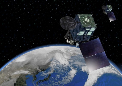
Himawari-8 and 9 (“sunflower”) are Geostationary Meteorological Satellites that form the third generation of Himawari satellites operated by the Japanese Meteorological Agency (JMA) for use in operational meteorological application. JMA began operating weather satellites in Geostationary Orbit in 1977 when the first generation of Himawari satellites was inaugurated known as GMS – Geostationary Meteorological Satellites.
Five GMS satellites were launched until the second generation of satellites, known as Multifunction Transport Satellites, began operation in 2005 using two Himawari satellites. The third generation of satellites will operate through 2031 with Himawari-8 launching in 2014 followed two years later by Himawari-9.
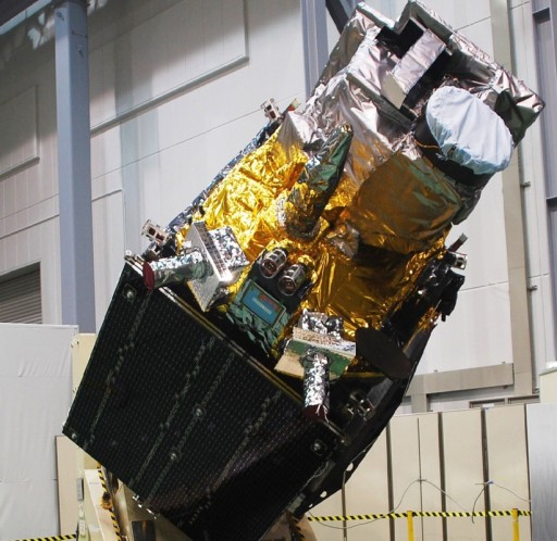
The Himawari-8 and 9 satellites are identical spacecraft, both built by Mitsubishi Electric for operation by the Japanese Meteorological Agency. Both satellites host one core instrument – the Advanced Himawari Imager, and two supporting instruments, the Space Environment Data Acquisition Monitor and the Data Collection Subsystem.
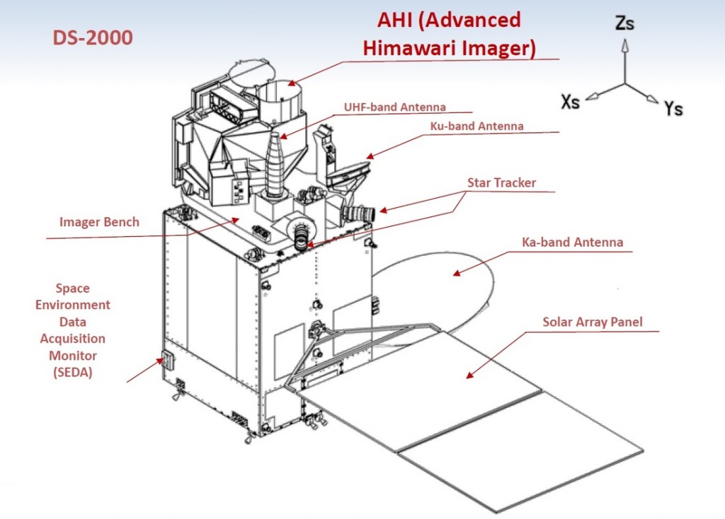
The satellites are based on Melco’s DS-2000 satellite bus that originated in a JAXA satellite design that was modified by Mitsubishi Electric to create a versatile Geostationary Satellite Platform that could support a variety of payloads. DS-2000 first flew in 2002 and has been used for a number of Geostationary Communication Satellites. The platform is also used for data relay spacecraft, weather satellites and future navigation satellites.
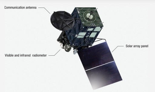
The satellite has a liftoff mass of 3,500 Kilograms, including 2,200 Kilograms of propellant. The spacecraft consists of a rectangular cuboid core structure that houses the majority of systems, a deployable solar array comprised of two panels, a deployable Ka-Band antenna and an imager bench that facilitates the main instrument and other satellite equipment. In its deployed configuration, the satellite measures 5.2 by 8.0 by 5.3 meters.
The single solar array consists of two panels and interfaces with a Solar Array Drive Mechanism to rotate the array for optimized solar illumination. Triple-junction gallium-arsenide solar cells are being used by the satellite. Overall, the array generates 2,600 Watts of End-of-Life power that is delivered to a Power Conditioning and Distribution Unit which controls the state of charge of a Li-Ion battery and conditions a regulated 100-Volt power bus that implements redundancy to ensure all equipment of the satellite receives electrical power.
Spacecraft thermal control is accomplished using a combination of passive thermal control featuring blankets and multilayer insulation and active thermal control using thermally conductive coldplate assemblies, heat pipes and radiators installed on the space-facing side of the spacecraft. Heaters are used to maintain operating temperatures of electronics equipment when needed.
The Himawari-8 and 9 satellites are equipped with a number of attitude sensors. Coarse Sun Sensors are used for initial attitude acquisition and to keep the solar array pointing at the sun in spacecraft safe mode. The primary attitude sensors are two star trackers which acquire imagery of the sky that is analyzed by a software algorithm that compares the acquired star pattern with a catalog to precisely determine the spacecraft’s orientation in space. Each star tracker has a field of view of around ten degrees and uses a CCD detector operating at 1Hz.
In addition to the star trackers that require small body rates for acquisition, Himawari uses an Inertial Reference Unit and Gyroscopes to measure three-axis attitude and body rates during maneuvers and initial attitude acquisition.
Attitude control is accomplished by a Reaction Wheel Assembly. The reaction wheel assembly is a rotating inertial mass that is driven by a brushless DC motor that spins the wheel. When accelerating the wheel, the satellite body to which the wheels are directly attached will rotate to the opposite direction as a result of the introduced counter torque. Typically, RWAs include four wheels for three-axis control with one wheel as a spare.
Regular reaction wheel desaturations are performed by the attitude control thrusters of the satellite which are fired to counter torque that is introduced when the satellite de-spins the wheels to maintain safe operating speeds of the RWA at all times.
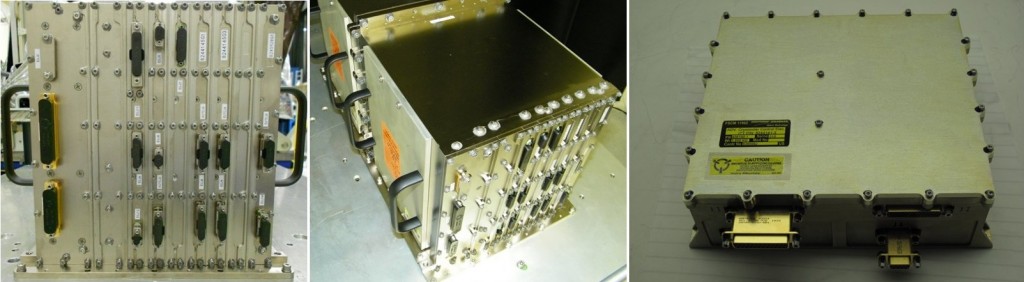
AHI Instrument Electronics & Cryocooler Electronics
Himawari-8 and 9 use a liquid-fueled propulsion system consisting of an Apogee Engine and a series of attitude control thrusters. The main engine is located on the opposite side to the imager bench and is used to perform a series of apogee maneuvers to boost the satellite from an elliptical Geostationary Transfer Orbit into a nearly circular Geostationary Orbit. Engine options available for the DS-2000 satellite bus are the 490-Newton R-4D and 450-Newton BT-4 engine, both use Monomethylhydrazine and Nitrogen Tetroxide/MON as propellants.
The satellite facilitates a Mission Data Handling Subsystem that interfaces with the main instrument via a SpaceWire bus to receive raw payload data that is processed onboard and sent to Earth through the communications subsystem of the spacecraft.
Himawari-8 and 9 use three different communication frequencies – Ku-Band, Ka-Band and UHF. A Ku-Band antenna is installed on the Imager Bench facing the Earth to provide Telemetry and Command services. Spacecraft commands are uplinked at a data rate of 500bit/s at a frequency of 13.75 to 14.5 GHz while the downlink of real time or stored telemetry and housekeeping data reaches 15.36kbit/s at a frequency of 12.2 to 12.75 GHz.
Ka-Band is exclusively used for the downlink of payload data via a large Ka-Band antenna deployed on one side panel of the spacecraft operating at a frequency of 18.1 to 18.4 GHz. The system reaches a data rate of 66Mbit/s for AHI payload data and 100 to 300 bit/s for Data Collection System packets. The downlink is modulated in QPSK with no encryption being employed.
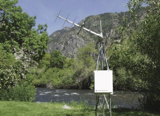
A UHF antenna is installed on the Imager Bench to receive messages from Data Collection Platforms deployed in remote locations on Earth. DCPs can be deployed virtually at any location on the globe to provide in-situ measurements of meteorological data that is then uplinked to satellites and transmitted to ground stations for collection, processing and distribution. The DCPs operate in the UHF band at 401/402 MHz.
These platforms include remote weather stations, buoys at sea to measure sea state and alert in the event of tsunamis as well as other measurement stations that are deployed in remote locations. Data received via the DCS UHF antenna at data rates of 100 to 300bit/s is relayed to the ground via the Ka-Band antenna for processing and distribution.
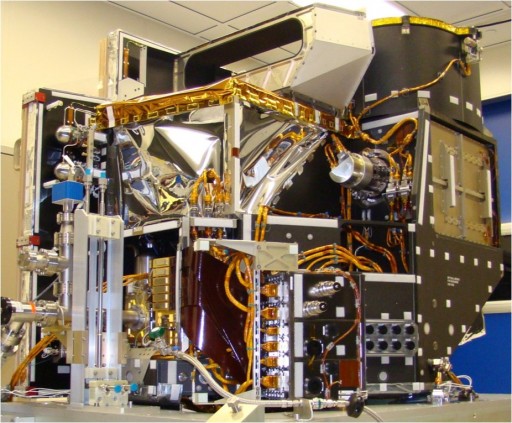
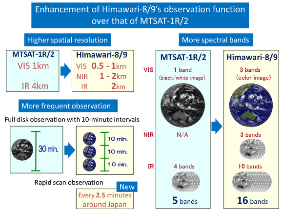
The main instrument of the Himawari-8 and 9 spacecraft is the Advanced Himawari Imager – a multispectral imaging payload developed by Exelis. It covers 16 spectral channels from the visible spectrum into the infrared wavelengths marking a major increase in channels compared to heritage instruments. AHI’s improved data quality will enable better nowcasting, improved numerical weather prediction accuracy and enhanced environmental monitoring.
The imager uses a continuous imaging technique for East-West-Imaging and South-North Stepping at swath width of 500 Kilometers. The instrument incorporates a cryocooler built by Northrop Grumman that keeps the infrared detectors at cryogenic temperatures for more than eight years to reduce dark currents.
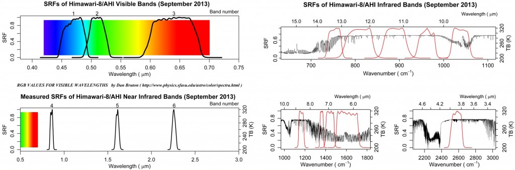
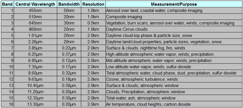
Three visible bands are covered by AHI, a blue band at 455 nanometers with a bandwidth of 50nm, a green band at 510nm with a bandwidth of 20nm and a red band at 645nm covering a bandwidth of 30nm. These three bands will be used to create RGB composite images. The blue and green channels deliver imagery at a spatial resolution of 1 Kilometer while the red channel achieves a ground resolution of 500 meters that will enable it to be used in vegetation monitoring, burn scar tracking, aerosol monitoring and wind assessment.
One Near-Infrared channel at 860nm will be used for cirrus cloud monitoring in daylight while two Shortwave Infrared will allow an assessment of cloud tops, particle size and snow. Four channels in the Mid-Infrared Range and six channels in the Longwave Infrared region serve a number of purposes.
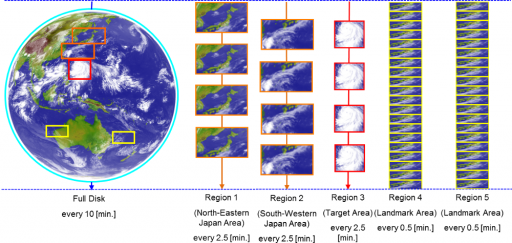
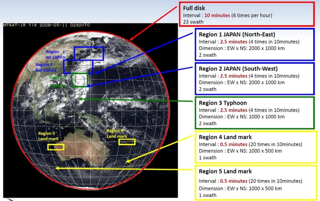
The main payload operates on a 10-minute timeline when in nominal operations mode. This timeline includes the acquisition of different images at varied intervals. Full-disk images of the entire planet as seen by the instrument are acquired once every ten minutes requiring 23 South-North Swaths to be taken.
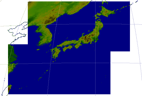
Three regional frames will be acquired every 2.5 minutes. Region 1 stretches 2,000 Kilometers from east to west and 1,000 Kilometers from north to south covering the north-eastern portion of Japan. Region 2 covers south-west Japan with the same dimensions as the first region to allow AHI to obtain imagery of the Japanese territory every two and a half minutes. These two regions are fixed in position.
Region 3 is 1,000 by 1,000 Kilometers in size, also requiring 2 image swaths acquired every 2.5 minutes. Unlike the first two regional images, Region 3 can be targeted as needed in order to allow AHI to obtain imagery of targets of special focus such as Typhoons.
Two Land Mark Regions are also part of the 10-minute routine – these images are taken every 30 seconds and only require one swath to be acquired since the images cover a ground region of 1,000 by 500 Kilometers.
Land Mark regions are flexible, but will initially be fixed to serve as navigation references. Later in the mission, these regions may be assigned to targets for the study of rapidly developing cumulonimbus clouds and other phenomena.
This results in 49 images taken per 10-minute timeline or 7,056 images returned per day without outages due to housekeeping operations.
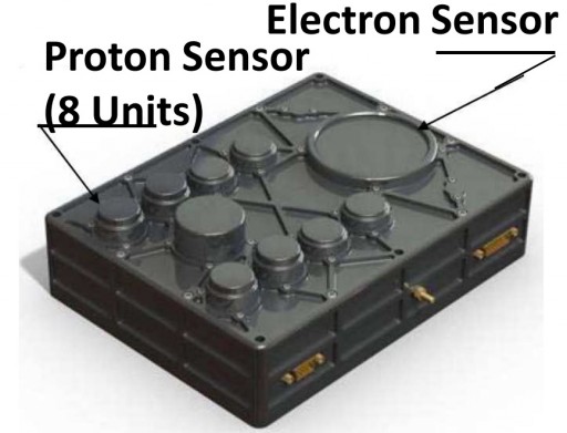
The third payload carried on Himawari-8 and 9 is the Space Environment Data Acquisition Monitor, SEDA, which will measure the radiation the satellites are exposed to in their Geostationary Position at 140 degrees East, 35,786 Kilometers above Earth.
The compact sensor features plug and play interfaces for integration on a variety of satellite platforms to create an operational constellation of space weather monitoring assets.
The sensor includes eight channels for protons consisting of eight individual sensor elements, and a single eight-channel electron sensor. Protons at energy ranges from 15 Mega-Electronvolt to 100 MeV are covered by the sensors while the energy range for electrons stretches from 0.2 MeV to 5 MeV.
The instrument delivers data at a temporal resolution of 10 seconds. The proton sensor has a field of view of +/-39.35 degrees while the electron sensor covers a FOV of +/-78.3 degrees. SEDA data is delivered to ground stations in real time for release as part of space weather reports used by satellite operators and scientists.
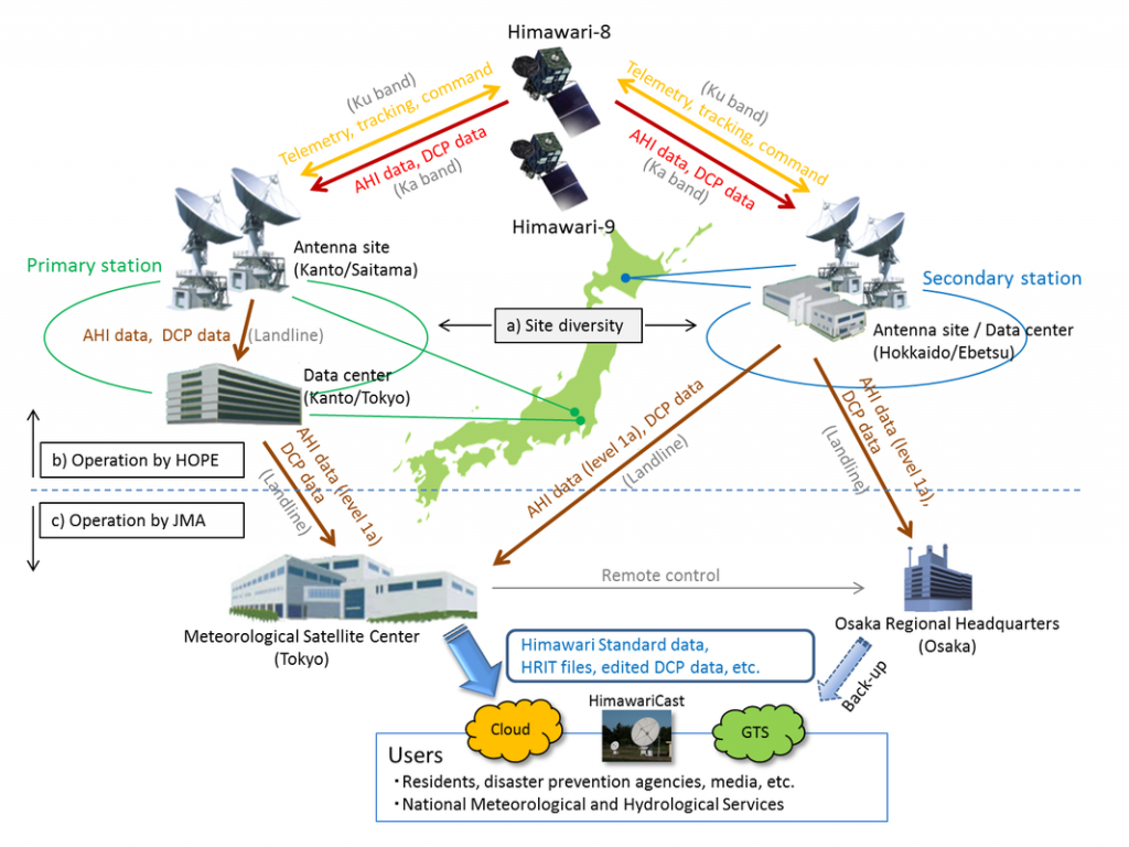
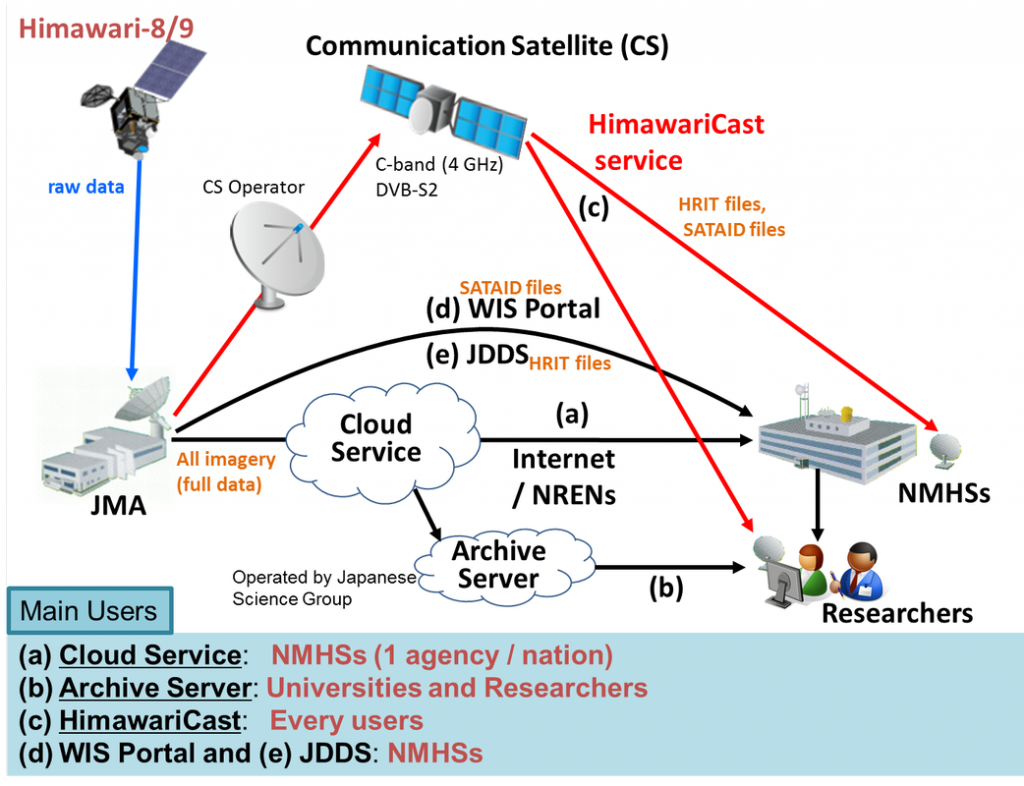
Data downlinked by the two Himawari satellites is received by one antenna at one of two dual-antenna ground stations located at Hiki-Gun, Saitama and Ebetsu, Hokkaido. Data is then processed in near-real time to deliver data products to users shortly after acquisition. Taking a new path in data distribution, JMA will upload all data sets to a cloud service that can be accessed by all users via the Internet. An archive server will be run by the Japanese Science Group to provide access to all past data sets returned by the satellites.
An additional way to receive data will be via a Commercial Telecommunications Satellite. This CTS data distribution has been in place for decades and uses a commercial communication satellite (JCSAT-2A&B) in Geostationary Orbit to relay data from a CTS ground station to all users via C-Band. Users need a C-Band antenna, an appropriate LNB and DVB-S2 receiver to be able to receive High Rate Information Transmission (HRIT) and Low Rate Information Transmission (LRIT) imagery.
Full-disk observations will be delivered in a Himawari Standard Data Format containing data from all 16 bands at full resolution amounting to 329 GB of data per day. PNG composite images only including the visible channels will be generated as well for a total data of 49 GB per day.
HRIT data includes five channels (a VIS composite and 4 IR channels at 4 km resolution) for a total data volume of 41 GB per day while LRIT data contains four channels (VIS composite, 3 IR at 5 km resolution) for a total daily data volume of 432 MB.
Regional imagery acquired every 2.5 minutes is also distributed in standard format and PNG plus the NetCDF format reaching a daily data volume of 12 GB. Cut-out images of areas of interest will be distributed in PNG and JPEG formats. Numerical weather prediction products are produced every six hours, In-situ observations is published every 30 minutes and ASCAT ocean surface winds are published every half hour.
Data delivered by Himawari-8 and 9 is used for a number of operational meteorological applications (nowcasting and numerical forecasting) as well as scientific research focusing on weather, climate, environmental monitoring, vegetation and a number of other areas. Measurements delivered by the satellites include:
- Cloud cover
- Aerosols & volcanic ash distribution
- Sea surface temperature
- Winds
- Clouds type identification
- Cloud top height
- Normalized Difference Vegetation Index
- Sea-ice cover
- Cloud top temperature
- Earth surface albedo
- Land surface temperature
- Upward long-wave irradiance at Earth surface
- Cloud ice effective radius
- Aerosol effective radius
- Integrated water vapor
- Photosynthetically Active Radiation
- Cloud drop effective radius
- Soil moisture
- Snow cover
- Aerosol Optical Depth
- Fire temperature
- Fraction of Absorbed PAR
- Cloud optical depth
- Upward long-wave irradiance at TOA
- Short-wave cloud reflectance
- Fire radiative power
- Downward short-wave irradiance at Earth surface
- Aerosol column burden
- Aerosol type
- Upward short-wave irradiance at TOA
- Downward long-wave irradiance at Earth surface
- Ozone (total column)
- Aerosol mass mixing ratio
